Link, Trailing, Rear: Installation: Installation
 Courtesy of CHRYSLER GROUP, LLC
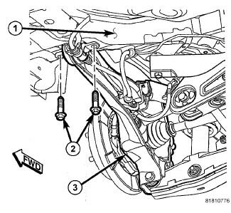
- Position the trailing link and install the two bolts (2) fastening the leading end of the trailing link (3) to the body (1). Tighten the two mounting bolts to 110 N.m (81 ft. lbs.).
 Courtesy of CHRYSLER GROUP, LLC
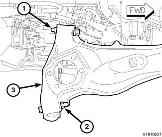
- Position the upper control arm on the trailing link (3) and install the bolt and nut (1) securing the arm to the link. Tighten the mounting bolt nut to 95 N.m (70 ft. lbs.).
- Position the lower control arm on the trailing link (3) and install the bolt and nut (2) securing the arm to the link. Tighten the mounting bolt nut to 95 N.m (70 ft. lbs.).
 Courtesy of CHRYSLER GROUP, LLC
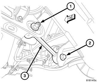
- Install the bolt (2) securing the toe link to the trailing link. To install the bolt it may be necessary to flex the trailing link body mount bushing inward or outward using an appropriate prying tool. Tighten the mounting bolt to 95 N.m (70 ft. lbs.).
 Courtesy of CHRYSLER GROUP, LLC
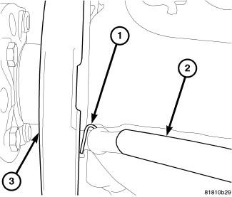
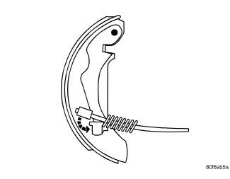
- Insert the parking brake cable through the trailing link from the inboard side.
- Slide the parking brake cable (2) into the brake support plate (3) with parking brake shoes.
- Install the hair pin (1) securing the parking brake cable (2) to the brake support plate (3).
 Courtesy of CHRYSLER GROUP, LLC
- Install the parking brake cable onto the lever on the parking brake shoe.
 Courtesy of CHRYSLER GROUP, LLC
- If equipped, position the wheel speed sensor (3) and install the screw (4) fastening the sensor to the trailing link (2). Tighten the mounting screw to 18 N.m (13 ft. lbs.).
- If equipped, position the wheel speed sensor (3) and install the routing clip (1) fastening the sensor to the trailing link (2).
- Install the hub and bearing, then install the brake rotor onto the wheel studs. Refer to HUB AND BEARING, INSTALLATION .
 Courtesy of CHRYSLER GROUP, LLC
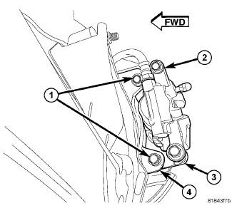
- Slide the disc brake caliper (2) and adapter (3) assembly over brake rotor and brake support plate.
- Install the two bolts (1) securing disc brake caliper adapter (3) to the brake support plate (4). Tighten the mounting bolts to 71 N.m (52 ft. lbs.).
 Courtesy of CHRYSLER GROUP, LLC
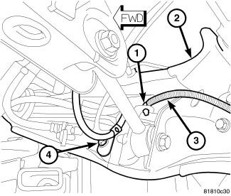
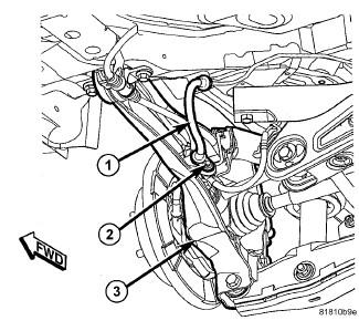
- Position the brake tube on the trailing link inserting the tube into the routing clip (2) and routing bracket over the welded stud.
- Install the nut (1) on the welded stud. Tighten the nut to 15 N.m (11 ft. lbs.).
 Courtesy of CHRYSLER GROUP, LLC
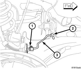
- Position the brake flex hose (1) at the trailing link (3) bracket and install the mounting screw (2). Tighten the screw to 23 N.m (17 ft. lbs.).
 Courtesy of CHRYSLER GROUP, LLC
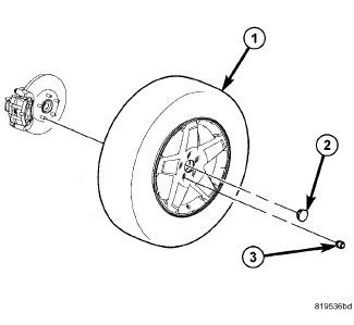
- Install the tire and wheel assembly (1). Refer to INSTALLATION
. Install and tighten the wheel mounting nuts (3) to 135 N.m (100 ft. lbs.).
- Lower the vehicle.
- Perform wheel alignment as necessary. Refer to WHEEL ALIGNMENT, STANDARD PROCEDURE
.