2.2L Diesel
 Courtesy of CHRYSLER GROUP, LLC
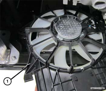
- Guide the cooling fan into position onto the radiator while clearing the upper radiator hose.
- Once into position, insert the lower tabs into the retainers.
- Install the bolts (1). Tighten to the proper SPECIFICATIONS .
- Remove the support and lower the vehicle.
 Courtesy of CHRYSLER GROUP, LLC
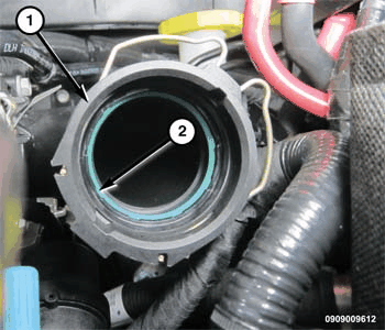
- Install a new O-ring seal (2) onto the EGR air flow control valve inlet tube (1).
 Courtesy of CHRYSLER GROUP, LLC
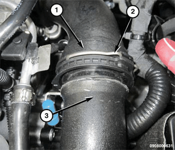
- Connect the Charge Air Cooler (CAC) hose (3) to the EGR air flow control valve inlet tube (1).
- Lock the CAC tube wire retainer (2).
 Courtesy of CHRYSLER GROUP, LLC
- Raise and support the vehicle.
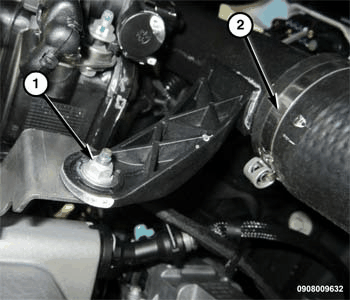
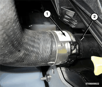
- Install the nut (1) securing CAC tube (2) to engine and tighten to the proper TORQUE SPECIFICATIONS - DIESEL
.
 Courtesy of CHRYSLER GROUP, LLC
- Connect the left CAC hose (1) to cooler (2).
- Install the belly pan. Refer to BELLY PAN, INSTALLATION
.
- Remove the support and lower the vehicle.
 Courtesy of CHRYSLER GROUP, LLC
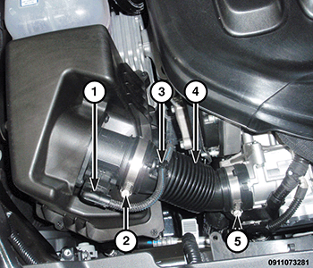
- Install the turbocharger inlet tube (4) and securely tighten clamps (2, 5).
- Connect the Mass Air Flow (MAF) sensor wire harness connector (1) and attach the wire (3) to the inlet tube.
 Courtesy of CHRYSLER GROUP, LLC
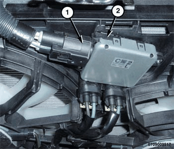
- Connect the cooling fan wiring harness connector (1).
- Install the engine cover. Refer to
- Connect the negative battery cable. If equipped with an Intelligent Battery Sensor (IBS), connect the IBS connector to the negative battery cable.