6F24 Power Flow
Hydraulic power flow is controlled by the TCM and the solenoids attached to the valve body. The TCM toggles control voltage or ground on and off in a duty cycle to regulate the line pressure flowing through the valve body. The lower the duty cycle percentage is the higher the line pressure. The pressure can be measured with (special tool #10424, Adapter, Transmission Pressure) and (special tool #C-3293-SP, Gauge, Pressure 0-300 P.S.I.).
 Courtesy of CHRYSLER GROUP, LLC
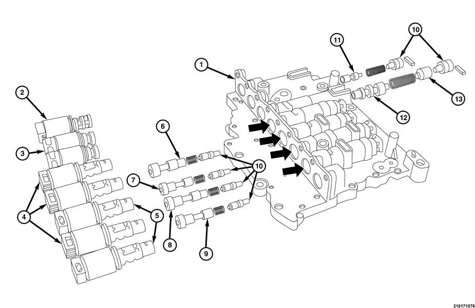
| 1= Outer Valve Body |
| 2= VFS Solenoid Valve NH |
| 3= On-Off Solenoid Valve |
| 4= VFS Solenoid Valve NH |
| 5= VFS Solenoid Valve NL |
| 6= Over Drive Pressure Control Valve |
| 7= Under Drive Pressure Control Valve |
| 8= 2-6 Brake Pressure Control Valve |
| 9= 3-5-R Pressure Control Valve |
| 10= Adjust Screws |
| 11= Reducing Valve |
| 12= Regulator Valve |
| 13= Regulator Sleeve |
| |
Solenoid |
Clutch/Brake |
| Gear |
OD (LR with SS-A) |
UD |
2/6 |
3/5/R (with SS-B) |
TCC |
LPS |
SS-A |
SS-B |
OD |
3/5/R |
2/6 |
L/R |
UD |
| |
Normal Open |
Normal Open |
Normal Closed |
Normal Open |
Normal Closed |
Normal Open |
Normal Closed |
Normal Closed |
|
| P |
7% |
42% |
7% |
41% |
7% |
45% |
82% |
OL (13.6V) |
|
|
|
50 psi |
|
| R |
7% |
42% |
7% |
6.80% |
7% |
8% |
82% |
82% (3V) |
|
230 psi |
|
230 psi |
|
| N |
7% |
42% |
7% |
42% |
|
45% |
82% |
OL |
|
|
|
50 psi |
|
| D1 |
7% |
7% |
13% |
42% |
|
45% @ idle (min pres.) 8% @ max pres. 36% @ 90 psi |
82% |
OL |
|
|
|
50 psi until ~5 mph |
|
| AS1 |
40% |
7% |
13% |
42% |
|
|
82% |
82% |
|
|
|
50 psi |
|
| AS2 |
40% |
7% |
39% |
42% |
|
|
OL |
OL |
|
|
50 psi |
|
|
| AS3 |
40% |
7% |
7% |
6.70% |
|
|
OL |
OL |
|
50 psi |
|
|
|
| AS4 |
7% |
7% |
7% |
40% |
|
|
OL |
OL |
51 psi |
|
|
|
|
| AS5 |
7% |
42% |
7.60% |
6.70% |
|
|
OL |
82% |
51 psi |
50 psi |
|
|
|
| AS6 |
7% |
42% |
39% |
41% |
|
|
OL |
OL |
51 psi |
|
50 psi |
|
|
| General Line Pressure Readings |
| LPS Duty Cycle (%) |
Pressure |
| 8% |
230 psi |
| 34% |
97 psi |
| 36% |
90 psi |
| 45% |
47-50 psi |
| Solenoid Reduced Circuit Feeds |
| RED 1 (SS-A/SS-B) |
73-75 psi max. |
| RED 2 (all other solenoids |
79-81 psi max. |
CLUTCHES/BRAKES
| Gear Range |
OWC |
Holding Brake |
Driving Clutch |
| Low/Rev |
Underdrive |
2/6 |
3/5/R |
Overdrive |
| P/N |
|
O |
|
|
|
|
| 1st |
O |
X |
O |
|
|
|
| 2nd |
|
|
O |
O |
|
|
| 3rd |
|
|
O |
|
O |
|
| 4th |
|
|
O |
|
|
O |
| 5th |
|
|
|
|
O |
O |
| 6th |
|
|
|
O |
|
O |
| Low |
|
O |
O |
|
|
|
| Rev |
|
O |
|
|
O |
|
| |
O = Applied |
X = Applied under certain conditions |
| |
ON/OFF |
Variable Force Solenoids |
| Gear |
SS/A-NC |
SS/B-NC |
UD-NO |
OD-NO |
3/5/R-NO |
2/6-NC |
LPS-NO |
TCC-NC |
| P/N |
O |
|
O |
|
O |
|
X |
|
| 1st |
X |
|
|
X |
O |
|
X |
|
| 2nd |
|
|
|
O |
O |
O |
X |
X |
| 3rd |
|
O |
|
O |
|
|
X |
X |
| 4th |
|
|
|
|
O |
|
X |
X |
| 5th |
|
O |
O |
|
|
|
X |
X |
| 6th |
|
|
O |
|
O |
O |
X |
X |
| Low |
O |
|
|
|
O |
|
X |
X |
| Rev |
O |
O |
O |
|
|
|
X |
X |
| |
O = Electric signal applied |
X = Electric signal may be applied for certain conditions |
| |
NO = Normally hydraulically open |
NC = Normally hydraulically closed |