2.2L Diesel
 Courtesy of CHRYSLER GROUP, LLC
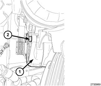
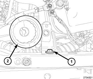
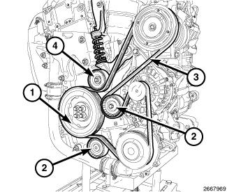
- Install the generator (1). Tighten bolt finger tight.
 Courtesy of CHRYSLER GROUP, LLC
- Install the bottom generator mounting retainer (2). Tighten upper and lower bolts to 28 N.m (21 ft. lbs.).
 Courtesy of CHRYSLER GROUP, LLC
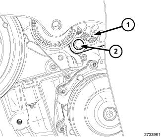
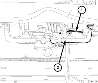
- Install the B+ cable. Tighten nut (2) to 10 N.m (89 in. lbs.).
- Connect the generator field wire harness connector (1).
 Courtesy of CHRYSLER GROUP, LLC
- Connect the upper radiator hose from the radiator.
- Install the A/C compressor. Refer to COMPRESSOR, A/C, INSTALLATION
.
 Courtesy of CHRYSLER GROUP, LLC
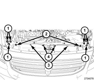
- Install the radiator core support.
 Courtesy of CHRYSLER GROUP, LLC
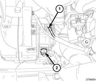
- Position the power steering reservoir (2) and securely tighten the bolt (1).
 Courtesy of CHRYSLER GROUP, LLC
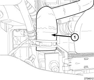
- Connect the hood release cable (1).
 Courtesy of CHRYSLER GROUP, LLC
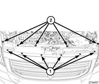
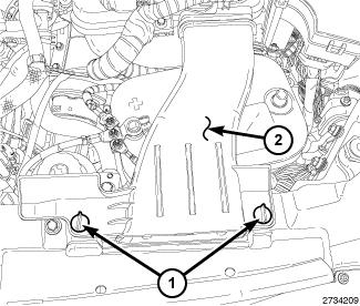
- Install the radiator support shroud.
 Courtesy of CHRYSLER GROUP, LLC
- Install the serpentine belt (3). Refer to BELT, SERPENTINE, INSTALLATION
.
- Evacuate and fill the cooling system. Refer to STANDARD PROCEDURE
.
 Courtesy of CHRYSLER GROUP, LLC
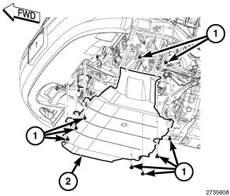
- If equipped, install the belly pan.
- Connect the negative battery cable.
 Courtesy of CHRYSLER GROUP, LLC
- Install the air inlet tube.