MANIFOLD, Intake: Installation: Installation
 Courtesy of CHRYSLER LLC
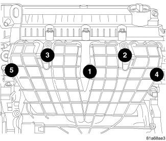
- Clean all gasket surfaces.
- Replace intake manifold gasket.
- Install intake manifold, tighten bolts to 25 N.m (220 in. lbs.).
 Courtesy of CHRYSLER LLC
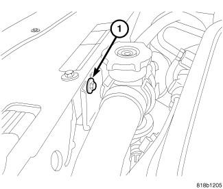
- Install the upper radiator hose retaining bracket (1).
 Courtesy of CHRYSLER LLC
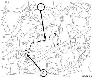
- Install the throttle body support bracket (1).
- Connect the electronic throttle control electrical connector.
- Install the wiring harness retainer to the intake manifold (2).
- Connect the MAP sensor electrical connector.
- Connect the vacuum lines to the intake manifold.
 Courtesy of CHRYSLER LLC
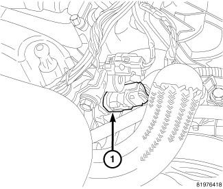
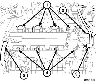
- Connect the oil temperature sensor (1).
- Connect the variable valve timing solenoid electrical connector.
- Connect the intake camshaft position sensor electrical connector.
 Courtesy of CHRYSLER LLC
- Install the fuel rail assembly to intake manifold. Tighten bolts to 23 N.m (200 in. lbs.).
- Connect fuel injector electrical connectors (4).
- Inspect quick connect fittings for damage, replace if necessary. Refer to STANDARD PROCEDURE - QUICK-CONNECT FITTINGS
. Connect fuel supply hose (3) to fuel rail assembly. Check connection by pulling on connector to insure it locked into position.
 Courtesy of CHRYSLER LLC
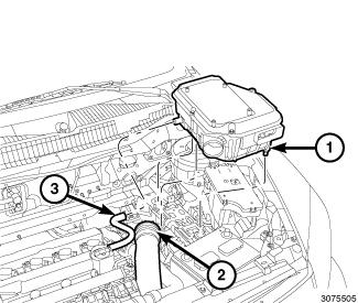
- Push down on the air cleaner body (1) to engage the pins into the grommets.
- Install the support bracket bolt to the strut tower and tighten to 10 N.m (89 in. lbs.).
- Install the air inlet tube (2) to the air cleaner body (1).
- Connect the make-up air hose (3) to the air cleaner body.
 Courtesy of CHRYSLER LLC
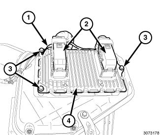
- Install the mounting bolt (3) with ground wire (1) and tighten to 12 N.m (106 in. lbs.).
- Connect and lock the electrical connectors (2).
 Courtesy of CHRYSLER LLC
- Connect the negative battery cable and tighten nut to 5 N.m (45 in. lbs.).
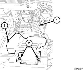
- Install the fresh air inlet duct (3) on the air cleaner body (1) and lock the retainers (2).
 Courtesy of CHRYSLER LLC
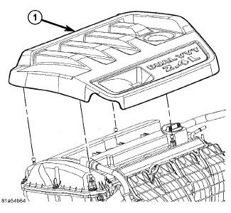
- Install the engine cover (1).