3.8L Engine
 Courtesy of CHRYSLER LLC
- Perform fuel pressure release procedure. Refer to STANDARD PROCEDURE
.
- Disconnect negative battery cable.
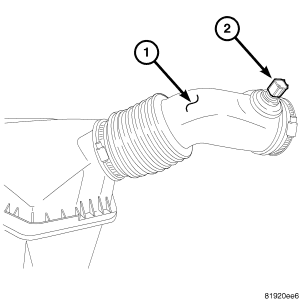
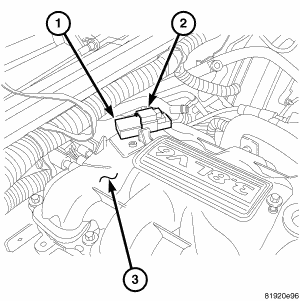
- Disconnect the Inlet Air Temp Sensor (IAT) (2), and remove air cleaner hose (1) and housing.
 Courtesy of CHRYSLER LLC
- Evacuate and recover the air conditioning.
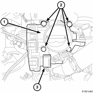
- Disconnect the throttle control connectors (3) from the throttle body.
 Courtesy of CHRYSLER LLC
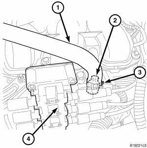
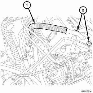
- Disconnect the PCV hose (1) at the left cylinder head cover.
 Courtesy of CHRYSLER LLC
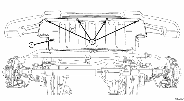
- Remove the front splash shield (1).
- Drain the cooling system.
- Disconnect the upper radiator hose from the thermostat housing and the lower radiator hose from the radiator.
- Disconnect the heater hoses and coolant reservoir hose.
 Courtesy of CHRYSLER LLC
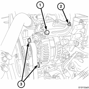
- Disconnect the generator electrical connectors (1,2).
 Courtesy of CHRYSLER LLC
- Disconnect the throttle position (TP), idle air control (IAC) motor, oxygen (HO2), cam position (CMP), manifold absolute pressure (MAP) (2) and the two engine wiring harness connectors. Free the harness from the cover studs and set harness aside.
- Disconnect the purge solenoid harness connector.
 Courtesy of CHRYSLER LLC
- Disconnect the EVAP hose from the throttle body.
- Remove the EGR tube (1). Refer to REMOVAL
.
 Courtesy of CHRYSLER LLC
- Remove the drive belts.
- Remove the generator (3).
 Courtesy of CHRYSLER LLC
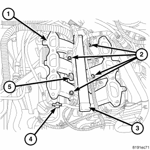
- Disconnect the fuel line from fuel rail (4).
- Remove engine wiring harness retainer from left cylinder head cover and oil level indicator tube.
Courtesy of CHRYSLER LLC
- Disconnect the knock sensor wiring harness connector.
- Remove the upper intake manifold (3).
 Courtesy of CHRYSLER LLC
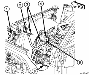
- Disconnect the A/C electrical connector.
- Disconnect the A/C discharge line (2) from the compressor. Cover and seal all openings of hoses and compressor.
 Courtesy of CHRYSLER LLC
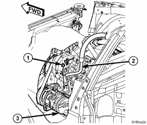
- Disconnect the A/C suction line (2) from the compressor. Cover and seal all openings of hoses and compressor.
 Courtesy of CHRYSLER LLC
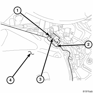
- Disconnect the oil pressure sending unit (OPS).
- Disconnect the coolant hose at the engine oil cooler.
- Remove the crankshaft sensor (2), (CKP).
 Courtesy of CHRYSLER LLC
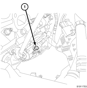
- Disconnect the in block heater (if equipped).
- Disconnect the starter wiring (1) and remove starter.
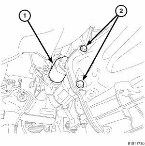 Courtesy of CHRYSLER LLC
- Remove the starter (1).
- Remove the flex plate inspection cover. (If equipped).
- Rotate the engine at the crankshaft pulley bolt and remove the torque converter bolts. (If equipped).
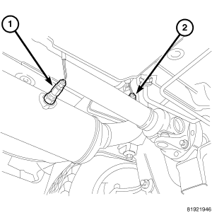 Courtesy of CHRYSLER LLC
- Disconnect the left side oxygen sensors (1,2).
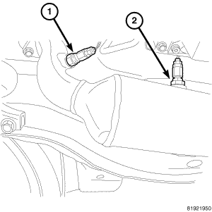 Courtesy of CHRYSLER LLC
- Disconnect the right side oxygen sensors (1,2).
- Disconnect the exhaust pipes from the manifolds.
- Remove the left and right exhaust manifolds.
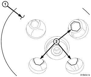 Courtesy of CHRYSLER LLC
- Remove the power steering pump mounting bolts (2) and pump, with hoses attached.
- Remove the engine mount thru bolts.
 Courtesy of CHRYSLER LLC
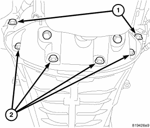
- Remove the structural cover mounting bolts (1,2), and cover. (If equipped).
- Support the transmission using a suitable jack.
- Connect engine lifting chain to engine, and lift the engine using a suitable hoist.
- Lift the engine using a suitable hoist.
- Separate the transmission from the engine.