- To install the control valve body assembly on to the transaxle case, insert a 75 mm (3 in.) long 3 mm (0.118 in.) wide rod or wire into the linkage stopper hole of the control valve assembly to set the pulley ratio linkage (1) in position. See Fig 1.
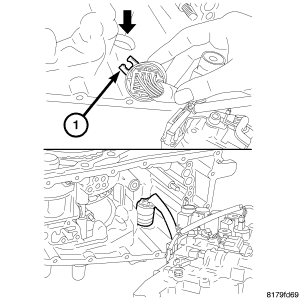 Courtesy of CHRYSLER LLC
- Position the locating tab (1) of the terminal body as shown in illustration and install the terminal body into the transaxle case. See Fig 2.
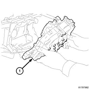 Courtesy of CHRYSLER LLC
- Install the control valve assembly (1) up from the bottom side and install it into the transaxle case. See Fig 3.
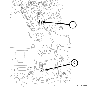 Courtesy of CHRYSLER LLC
- Align the notch (1) of the pulley ratio linkage with the sheave position sensor (2). See Fig 4.
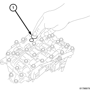 Courtesy of CHRYSLER LLC
CAUTION:
Apply CVT fluid when installing the bushing.
- Install the bushing (1) into the control valve assembly. See Fig 5.
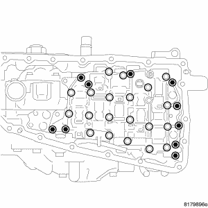 Courtesy of CHRYSLER LLC
- Tighten the mounting bolts of the control valve body assembly to 8 N.m (70 in. lbs).
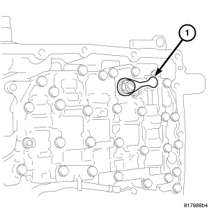 Courtesy of CHRYSLER LLC
- Install the manual lever (1) onto the manual shaft. Install and tighten the mounting nut to 22 N.m (16 in. lbs.). See Fig 7.
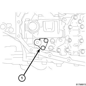 Courtesy of CHRYSLER LLC
- Install the bracket (1) onto the control valve assembly. Install and tighten the mounting bolts to 8 N.m (70 in. lbs.). See Fig 8.
 Courtesy of CHRYSLER LLC
CAUTION:
Do not re-use the o-ring. Apply CVT fluid when installing the o-ring.
- Install the new o-ring (1) onto the new oil strainer. See Figure.
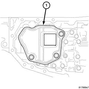 Courtesy of CHRYSLER LLC
- Install the new oil strainer (1) onto the control valve assembly. Install and tighten the mounting bolts to 8 N.m (70 in. lbs.). See Figure.
 Courtesy of CHRYSLER LLC
CAUTION:
Do not re-use the oil pan gasket. Remove any moisture, oil, and used gasket material from the surface where the new gasket is to be installed. When installing the oil pan gasket, align the dowel pin with the dowel pin hole in the oil pan gasket.
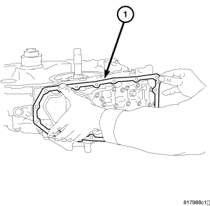
- Install the oil pan gasket (1) onto the transaxle case. See Figure.
 Courtesy of CHRYSLER LLC
CAUTION:
When installing the oil pan, align the dowel pin of the transaxle case with the dowel pin hole of the oil pan.
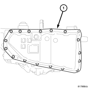
- Install the oil pan on the transaxle case (1). See Figure. Install and tighten the mounting bolts to 8 N.m (70 in. lbs.).
 Courtesy of CHRYSLER LLC
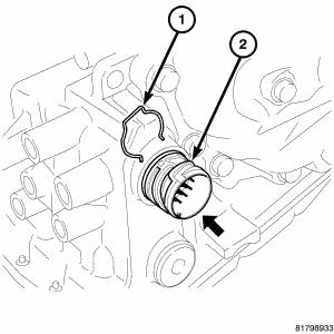
- Install the snap ring (1) onto the terminal body. See Fig 13.
- Fill transmission with the required fluid. See STANDARD PROCEDURE .