- Refer to the exploded views as necessary when performing the following steps.
 Courtesy of CHRYSLER LLC
- Drain the CVT fluid from the transaxle assembly.
- Remove the power transfer unit assembly and o-ring (4WD only).
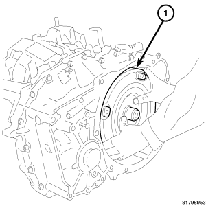
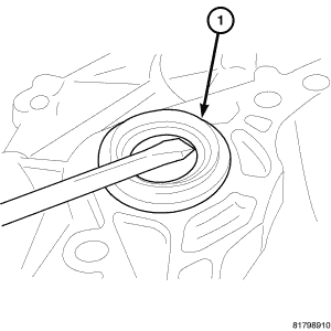
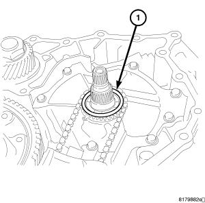
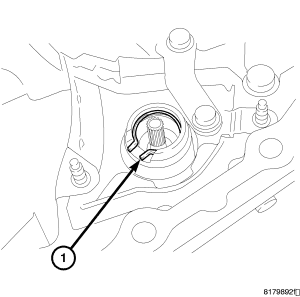
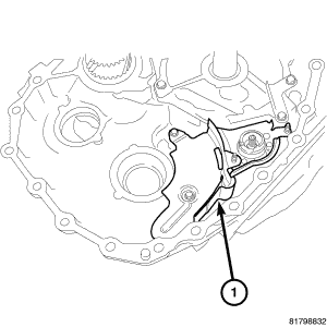
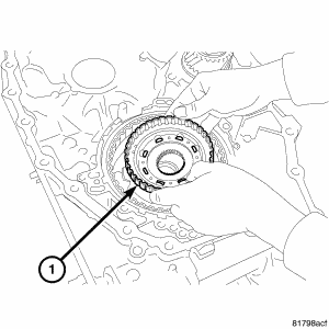
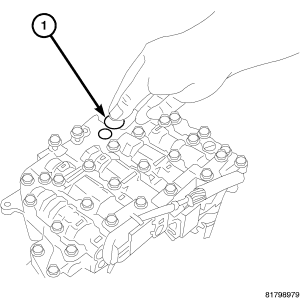
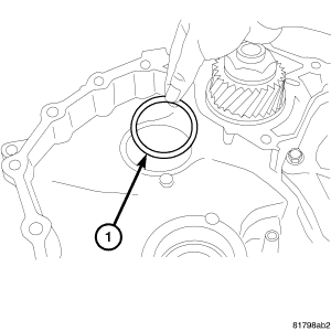
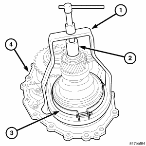
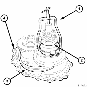
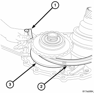
- Remove the torque converter (1) from the transaxle. See Fig 3.
 Courtesy of CHRYSLER LLC
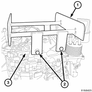
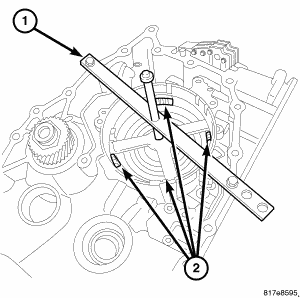
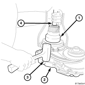
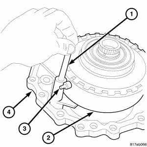
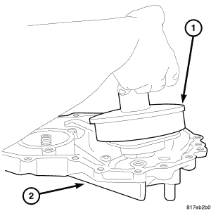
- Install Transmission Service Stand 9878 (1) to the belt side of the transmission case (3) using the upper transmission mount bolts (2).
 Courtesy of CHRYSLER LLC
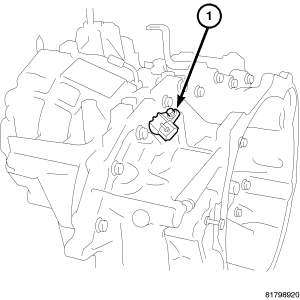
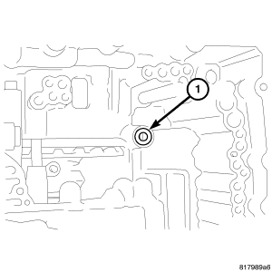
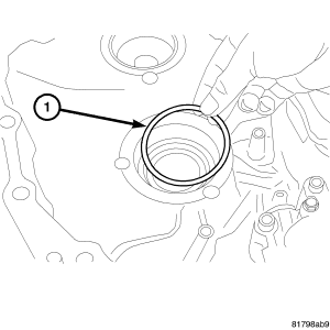
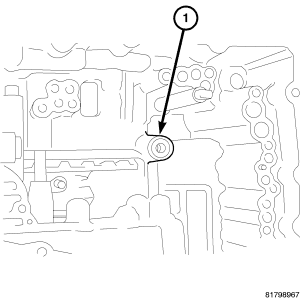
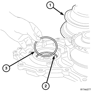
- Remove the output speed sensor (1) from the converter housing. Remove and discard the o-ring from the output speed sensor. See Fig 5.
CAUTION:
Set aside and reuse any adjusting shim found between the output speed sensor and the converter housing.
 Courtesy of CHRYSLER LLC
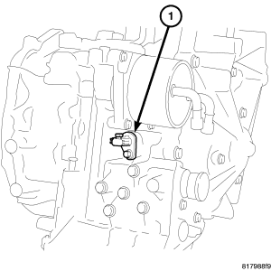
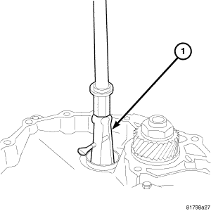
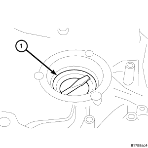
- Remove the input speed sensor (1) from the transaxle case. Remove and discard the o-ring from the input speed sensor. See Fig 6.
 Courtesy of CHRYSLER LLC
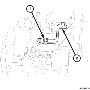
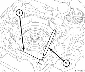
- Remove the nut (1) holding the shift lever (2) to the manual shaft.
- Remove the shift lever from the manual shaft. See Fig 7.
 Courtesy of CHRYSLER LLC
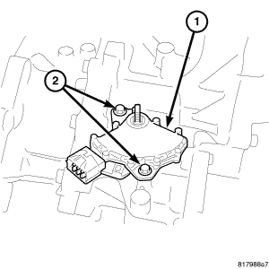
- Remove the bolts (2) holding the transmission range sensor (TRS) (1) to the transaxle case.
- Remove the (TRS) transmission range sensor (1) from the transaxle case and the manual shaft. See Fig 8.
 Courtesy of CHRYSLER LLC
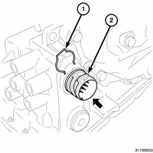
- Remove the snap ring (1) from the terminal body (2) and press the terminal body into the transaxle case. See Fig 9.
CAUTION:
Be careful not to cause damage to the terminal body.
 Courtesy of CHRYSLER LLC
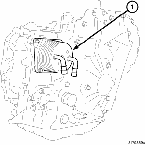
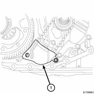
- Remove CVT fluid cooler (1) from transaxle case. Remove and discard the CVT fluid cooler o-ring. See Fig 10.
 Courtesy of CHRYSLER LLC
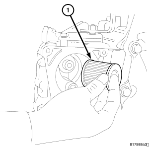
- Remove the bolts holding the CVT fluid filter to the transaxle case.
- Remove the CVT fluid filter (1) from the transaxle case. See Fig 11.
 Courtesy of CHRYSLER LLC
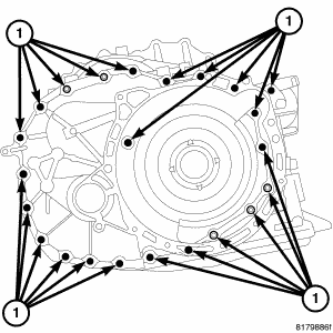
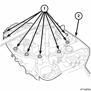
- Remove the converter housing mounting bolts. See Fig 12.
 Courtesy of CHRYSLER LLC
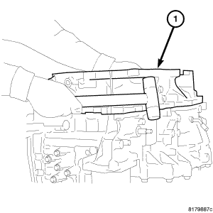
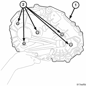
- Remove the converter housing (1) by tapping with plastic hammer. See Fig 13.
CAUTION:
There is a possibility that the drive sprocket adjusting shim may be dislodged and fall out.
 Courtesy of CHRYSLER LLC
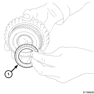
- Remove outer race of reduction gear bearing (1) from the converter housing using Puller 7794-A and Puller C-637. See Fig 14.
 Courtesy of CHRYSLER LLC
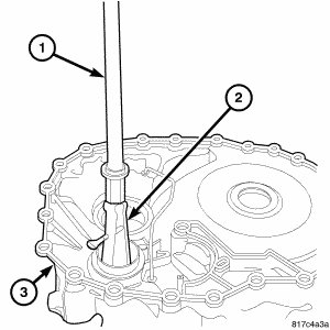
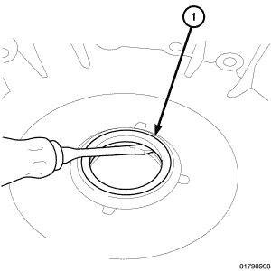
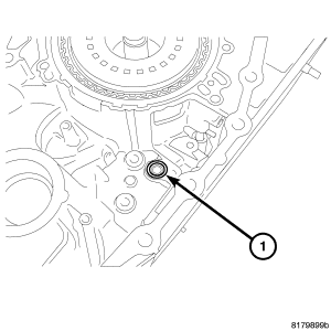
- Remove differential side oil seal (1) from converter housing using a screwdriver. (2WD) See Fig 15.
 Courtesy of CHRYSLER LLC
- Remove converter housing oil seal (1) from converter housing using a screwdriver. See Fig 16.
 Courtesy of CHRYSLER LLC
- Remove outer race (1) of differential side bearing from converter housing using a suitable punch. See Fig 17.
CAUTION:
When removing the outer race, tap the outer race on both sides evenly. When removing the outer race, do not damage the converter housing.
 Courtesy of CHRYSLER LLC
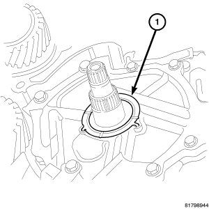
- Remove and discard the O-ring (1) from the input shaft. See Fig 18.
 Courtesy of CHRYSLER LLC
- Remove the adjusting shim (1) from the drive sprocket, if necessary. See Fig 19.
 Courtesy of CHRYSLER LLC
- Remove the nuts holding the baffle plate (1) to the transaxle. See Fig 20.
- Remove the baffle plate.
 Courtesy of CHRYSLER LLC
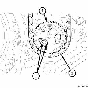
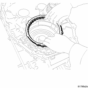
- Expand the snap ring (1) and remove the driven sprocket (3), the oil pump chain (2), and the drive sprocket. See Fig 21.
 Courtesy of CHRYSLER LLC
- Remove the thrust washer (1) from the oil pump cover. See Fig 22.
 Courtesy of CHRYSLER LLC
- Remove the snap ring (1) from the oil pump. See Fig 23.
 Courtesy of CHRYSLER LLC
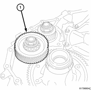
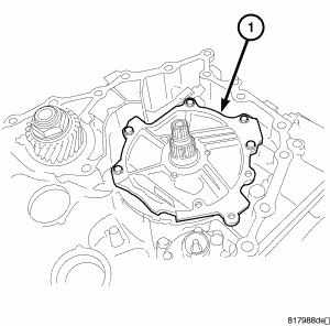
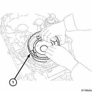
- Remove the reduction gear assembly (1) from the transaxle case. See Fig 24.
 Courtesy of CHRYSLER LLC
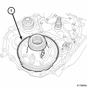
- Remove the differential assembly (1) from the transaxle case. See Fig 25.
 Courtesy of CHRYSLER LLC
- Remove the bolts holding the bracket (1) to the oil pump cover and the transaxle. See Fig 26.
- Remove the bracket (1).
 Courtesy of CHRYSLER LLC
- Remove the bolts holding the baffle plate (1) to the transaxle. See Fig 27.
- Remove the baffle plate.
 Courtesy of CHRYSLER LLC
- Remove the bolts holding the reaction shaft support (1) to the transaxle. See Fig 28.
- Remove the reaction shaft support from the transaxle case.
 Courtesy of CHRYSLER LLC
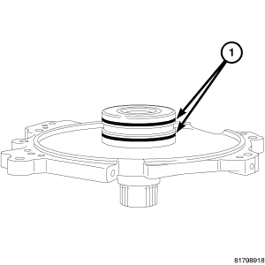
- Remove and discard the seal rings (1) from the reaction shaft support. See Fig 29.
 Courtesy of CHRYSLER LLC
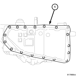
- Remove the bolts holding the oil pan (1) to the transaxle case. See Fig 30.
- Remove the oil pan from the transaxle case.
 Courtesy of CHRYSLER LLC
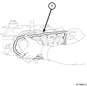
- Remove the oil pan gasket (1) from the transaxle case. See Fig 31.
 Courtesy of CHRYSLER LLC
- Remove the bolts holding the oil strainer (1) to the valve body. See Fig 32.
- Remove the oil strainer.
- Remove and discard the oil strainer o-ring.
 Courtesy of CHRYSLER LLC
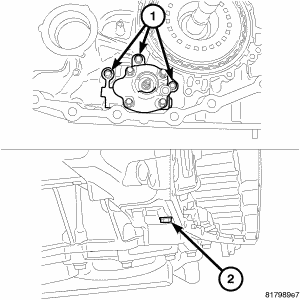
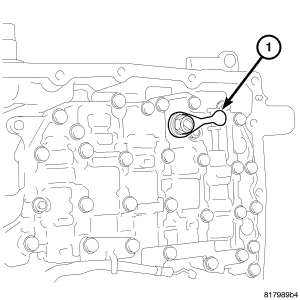
- Remove the bolt (2) holding the oil pump to the transaxle case from the rear of the transaxle. See Fig 33.
- Remove the bolts (1) holding the oil pump to the transaxle case from inside the transaxle.
- Remove the oil pump from the transaxle case.
 Courtesy of CHRYSLER LLC
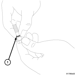
NOTE:
One of the oil pump retaining bolts is installed from the outside of the transaxle case into the rear part of the oil pump.
- Remove and discard the o-ring (1) from the oil pump mounting bolt. (Only on bolt installed from the outside of the transaxle case).
 Courtesy of CHRYSLER LLC
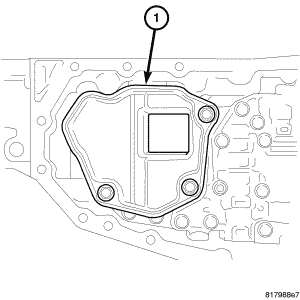
- Remove and discard the lip seal (1) from the transaxle case. See Fig 35.
 Courtesy of CHRYSLER LLC
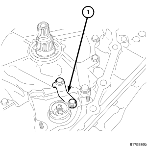
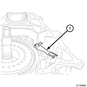
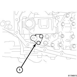
- Remove the bolt holding the detent spring (1) to the transaxle case. See Fig 36.
- Remove the detente spring from the transaxle case.
 Courtesy of CHRYSLER LLC
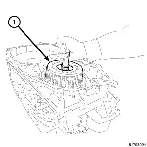
- Remove the forward clutch assembly (1) from the transaxle case. See Fig 37.
 Courtesy of CHRYSLER LLC
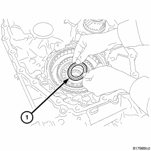
- Remove needle bearing (1) from forward clutch drum side of the sun gear. See Fig 38.
 Courtesy of CHRYSLER LLC
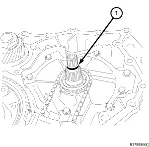
- Remove the sun gear (1) from the planetary carrier. See Fig 39.
 Courtesy of CHRYSLER LLC
- Remove the needle bearing (1) from the sun gear. See Fig 40.
 Courtesy of CHRYSLER LLC
- Remove the planetary carrier assembly (1) from the transaxle case. See Fig 41.
 Courtesy of CHRYSLER LLC
- Remove the needle bearing (1) from the planetary carrier. See Fig 42.
 Courtesy of CHRYSLER LLC
- Remove the bolts holding the bracket (1) to the valve body assembly. See Fig 43.
- Remove the bracket from the valve body assembly.
 Courtesy of CHRYSLER LLC
- Remove the nut holding the manual lever (1) to the manual shaft. See Fig 44.
- Remove the manual lever.
 Courtesy of CHRYSLER LLC
- Use this picture when removing valve body attaching bolts.
 Courtesy of CHRYSLER LLC
CAUTION:
Tilt the valve body assembly away from the transaxle case on the manual shaft side to ease removal. Pay attention to completely remove the terminal body from the transaxle case.
- Remove the valve body assembly from the transaxle case as follows:
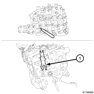
- Insert a 75 mm (3 in.) long 3 mm (0.118 in.) wide rod or wire into the linkage stopper hole of the valve body assembly to fix the pulley ratio linkage (1). See Fig 46.
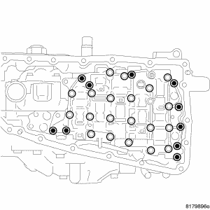
- Remove the bolts holding the valve body assembly to the transaxle case.
- Remove the valve body assembly from the transaxle case.
 Courtesy of CHRYSLER LLC
- Remove and set aside the bushing (1) from the valve body. See Fig 47.
 Courtesy of CHRYSLER LLC
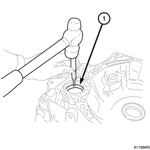
- Remove the pin at the manual shaft using a punch (2). See Fig 48.
- Remove the manual shaft from case.
 Courtesy of CHRYSLER LLC
- Remove and discard the lip seal (1) from the transaxle case. See Fig 49.
 Courtesy of CHRYSLER LLC
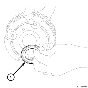
- Remove outer race (1) of differential side bearing from converter main housing using Puller 9664 and Puller C-637. See Fig 50.
 Courtesy of CHRYSLER LLC
- Remove the selective shim (1) from the transaxle case. See Fig 51.
Courtesy of CHRYSLER LLC
- Remove outer race of reduction gear bearing (1) from transaxle case using Puller C-637 and Puller 7794-A. See Fig 52.
 Courtesy of CHRYSLER LLC
- Remove the selective shim (1) from the transaxle case. See Fig 53.
 Courtesy of CHRYSLER LLC
CAUTION:
When removing the side oil seal, do not damage the transaxle case.
- Remove side oil seal (1) from transaxle case using a screwdriver. See Fig 54.
 Courtesy of CHRYSLER LLC
CAUTION:
Check if there is damage, deformation, or burning on the surface of any of the drive or driven plates. Check for permanent fatigue of the dish plate, driven plates, retaining plate, snap ring, and the drive plates. Replace all reverse brake components if any of these conditions exist.
- Remove the reverse brake snap ring using a screwdriver. Then remove the reverse brake retaining plate, the drive plates, the driven plates, and the dish plate from the transaxle case. See Fig 55
 Courtesy of CHRYSLER LLC
CAUTION:
Set the spring compressor right on top of the return spring of the spring retainer assembly. Do not remove the return springs from the spring retainer assembly.
- Compress the reverse brake return spring using Compressor 5058A (1) and Compressor 9875. Remove the snap ring (2) from the transaxle case. See Fig 56.
- Remove the retaining plate and the spring retainer assembly.
 Courtesy of CHRYSLER LLC
CAUTION:
There is a possibility that the reverse brake piston might be stuck if excessive pressure is required to remove.
- Try removing the reverse brake piston from the transaxle case by hand if unable to remove by hand, apply compressed air to the fluid passage (1) and remove the reverse brake piston from the transaxle case. See Fig 57.
 Courtesy of CHRYSLER LLC
- Remove the case bolts (1) at the drive belt assembly (2). See Fig 58.
NOTE:
Pin at pulley sensor stays with drive belt assembly case.
- Separate drive belt assembly case from main housing.
 Courtesy of CHRYSLER LLC
- Remove the bolts (2) that hold both sheaves to the case (1). See Fig 59.
 Courtesy of CHRYSLER LLC
CAUTION:
Do not allow the Puller 9874 to come in contact with the belt at any time
- Install the Puller 9874 (1) and Insert 8513A (2) onto the secondary sheave (3).
 Courtesy of CHRYSLER LLC
CAUTION:
Do not over tighten the compressor tool. Tighten to no more than 7 N.m (50 in. lbs.)
NOTE:
The belt is directional, look for an arrow indicating the direction of the belt for installation
- Compress sheave (2) to the stop.
 Courtesy of CHRYSLER LLC
CAUTION:
Do not allow the primary sheave to contact the drive surface of the secondary sheave.
NOTE:
You may need to lightly tap case while holding secondary sheave.
- Lift and move the secondary sheave (1) closer to the primary sheave.
 Courtesy of CHRYSLER LLC
- Remove the pin (1) from the sheave height sensor (3).
 Courtesy of CHRYSLER LLC
- Lift the primary sheave (3) enough to remove the sheave height sensor (1).
 Courtesy of CHRYSLER LLC
- Remove the drive belt (1) from both secondary (3) and primary sheaves (2).
- Remove the secondary sheave.
 Courtesy of CHRYSLER LLC
- Remove the shim (3) under the secondary sheave (1).
 Courtesy of CHRYSLER LLC
- Remove the primary sheave.
- Remove bolts at the park pawl.
- Remove the park pawl.