- Refer to the exploded views as necessary when performing the following steps.
 Courtesy of CHRYSLER LLC
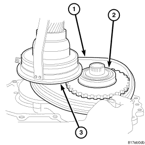
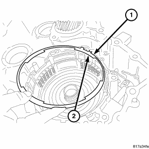
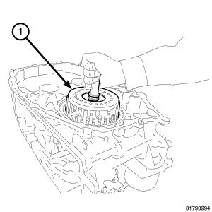
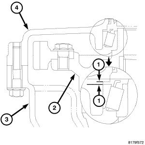
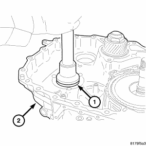
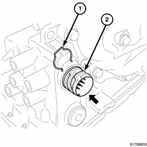
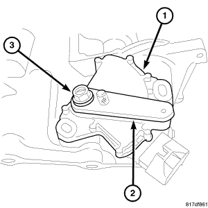
- Install the primary sheave (2) with the sheave height sensor, (3) spring and pin (1) into the belt side case.
 Courtesy of CHRYSLER LLC
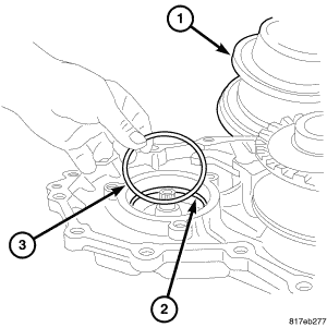
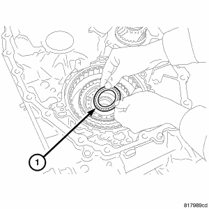
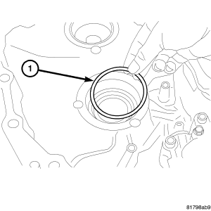
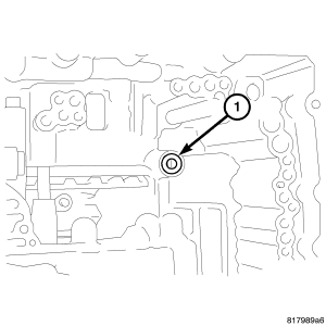
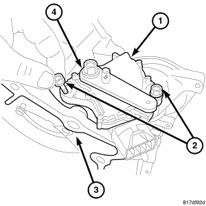
- Install the secondary sheave positioning shim (3) into the belt side cover.
 Courtesy of CHRYSLER LLC
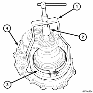
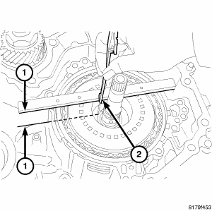
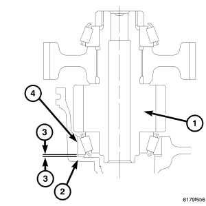
- Install Puller 9874 (1) and Insert 8513 A, (2) onto secondary sheave.
 Courtesy of CHRYSLER LLC
- Move the secondary sheave (3) close enough to the primary (2) sheave to allow the drive belt (1) to be put around both secondary and primary sheaves.
NOTE:
The drive belt is directional and will need to be installed in the same direction as noted in disassembly. if installed incorrectly failure will occur.
- Install the drive belt (1).
CAUTION:
Do not over tighten the compressor tool. Tighten to no more than 7 N.m (50 in. lbs.).
- Compress the secondary (3) sheave to the stop.
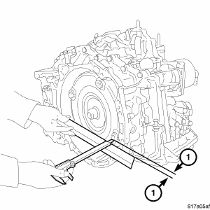
- Install the drive belt (1) around both secondary (3) and primary (2) sheaves.
- Install the primary sheave into place.
- Remove Puller 9874 and Insert 8513A from the primary sheave.
 Courtesy of CHRYSLER LLC
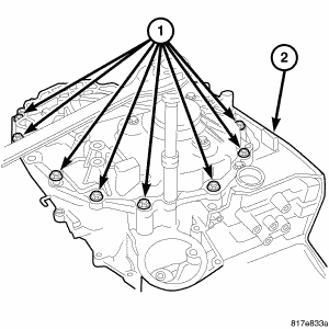
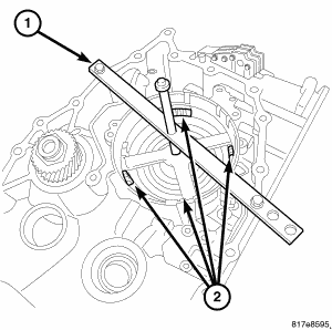
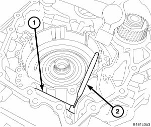
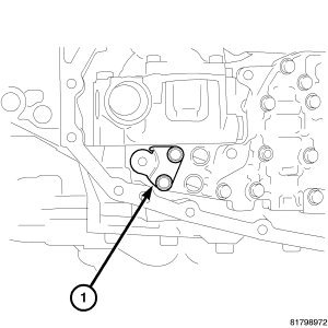
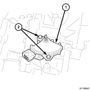
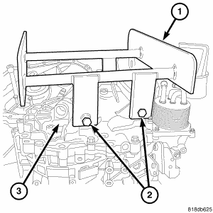
- Install the bolts (2) that hold both sheaves to the case (1).
 Courtesy of CHRYSLER LLC
CAUTION:
Remove moisture, oil, and used sealant from the sealant application surface. Make sure that the starting point and the ending point are between two bolt holes.
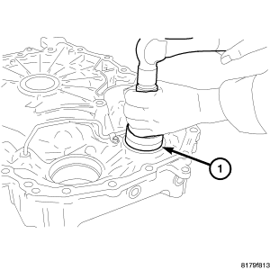
- Apply Loctite 509 sealer onto the belt side of the transaxle case.
- Install the belt side assembly to the transaxle case.
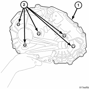
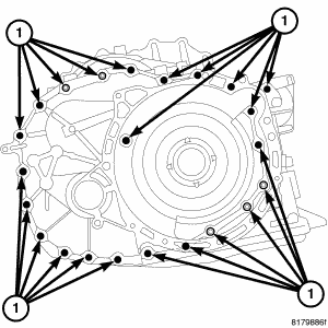
- Install the case bolts (1) to hold the drive belt assembly (2) to the transaxle. tighten to 45 N.m (33 ft. lbs.).
 Courtesy of CHRYSLER LLC
CAUTION:
Inspect the reverse brake piston and, if damaged, replace it before installation. Apply CVT fluid to the seal when installing the reverse brake piston.
NOTE:
Rotate reverse brake piston into place.
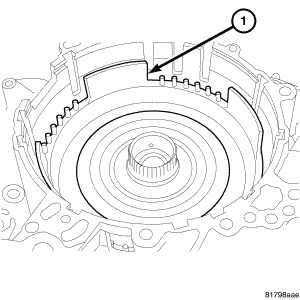
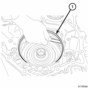
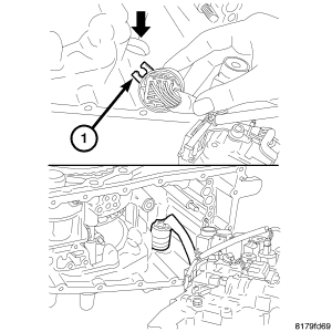
- Rotate and install the reverse brake piston (1) into the transaxle case. See Fig 9.
 Courtesy of CHRYSLER LLC
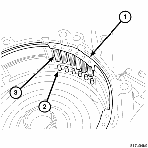
- Align the return springs (3) of the spring retainer assembly (1) to the locating posts (2) of the reverse clutch piston. See Fig 10.
 Courtesy of CHRYSLER LLC
NOTE:
There is a notch in the retaining plate that points to the top of the case.
- Install the retaining plate (1) into the transaxle case with the notch on the plate to the top (2). See Fig 11.
 Courtesy of CHRYSLER LLC
CAUTION:
Set the spring compressor on top of the spring retainer assembly.
- Compress the reverse brake return spring using Compressor 5058 A (1) and Compressor 9875 and install the snap ring into the transaxle case using a screwdriver. See Fig 12.
 Courtesy of CHRYSLER LLC
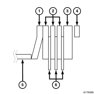
- Install the dish plate (1) with the convex side down onto the reverse brake piston.
- Install driven plate (2) and then a drive plate (6) until all the driven and drive plates are installed.
- Install the retaining plate (3) into the reverse brake assembly.
- Install the reverse brake snap ring (4) into the transaxle case.
 Courtesy of CHRYSLER LLC
CAUTION:
When conducting measurements, measure two or more places and calculate the average value.
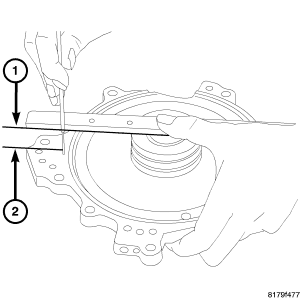
- Measure the clearance between the snap ring and the retaining plate (1). See Fig 14. The correct clutch clearance is 1.2-1.5 mm (0.047-0.059 in.). If the clutch clearance is not within specifications, measure the existing retaining plate and select the correct retaining plate.
 Courtesy of CHRYSLER LLC
CAUTION:
Apply Vaseline or assembly lube when installing the needle bearing. Be careful to verify correct orientation of the needle bearing when installing it.
NOTE:
The inner race will need to face down.
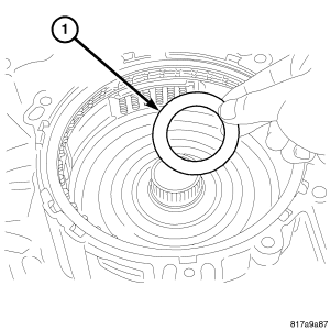
- Install the needle bearing (1) onto the reverse brake piston. Check for the direction of the needle bearing while installing. See Fig 15.
 Courtesy of CHRYSLER LLC
NOTE:
The inner race will need to face down
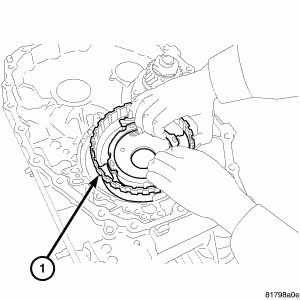
- Install the planetary carrier assembly (1) onto the reverse brake. See Fig 16.
 Courtesy of CHRYSLER LLC
CAUTION:
Apply Vaseline or assembly lube when installing the needle bearing. Be careful to verify correct orientation of the needle bearing when installing it.
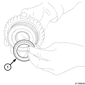
- Install the needle bearing (1) onto the primary pulley side of the sun gear. See Fig 17.
 Courtesy of CHRYSLER LLC
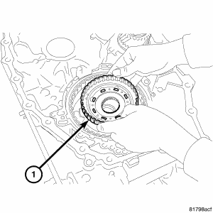
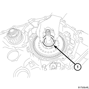
- Install the sun gear (1) onto the planetary carrier. See Fig 18.
 Courtesy of CHRYSLER LLC
CAUTION:
Apply Vaseline or assembly lube when installing the needle bearing. Be careful to verify correct orientation of the needle bearing when installing it.
NOTE:
The inner race will need to face up.
- Install the needle bearing (1) on the forward clutch drum side of the sun gear. See Fig 19.
 Courtesy of CHRYSLER LLC
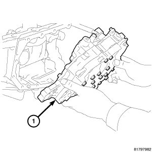
- Install the forward clutch assembly (1) into the transaxle case. See Fig 20.
 Courtesy of CHRYSLER LLC
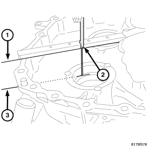
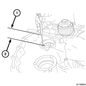
- Measure the total end play (2) in the following steps. Total end play should be 0.25 - 0.55 mm (0.010 - 0.022 in).
 Courtesy of CHRYSLER LLC
NOTE:
Gauge Bar 6311 can be used for doing the following measurement.
- Measure the distance (1) from the oil pump cover installation surface of the transaxle case to the needle bearing installation surface of the forward clutch drum. Call this measurement one.
 Courtesy of CHRYSLER LLC
NOTE:
Gauge Bar 6311 can be used for doing the following measurement.
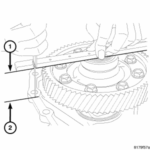
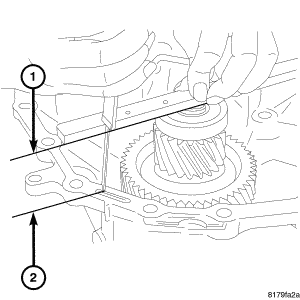
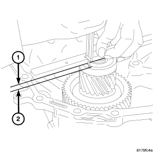
- Measure the distance (1 to 2) as shown in illustration. Call this measurement two.
- Calculate the bearing thickness required to achieve the necessary end play with the following formula. The bearing thickness is equal to measurement one, minus measurement two minus, the nominal end play (0.40 mm or 0.016 "in).
 Courtesy of CHRYSLER LLC
CAUTION:
Apply Vaseline or assembly lube when installing the needle bearing. Be careful to verify correct orientation of the needle bearing when installing it.
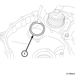
- Install the selected needle bearing (1) on the forward clutch assembly. See Fig 24.
 Courtesy of CHRYSLER LLC
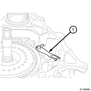
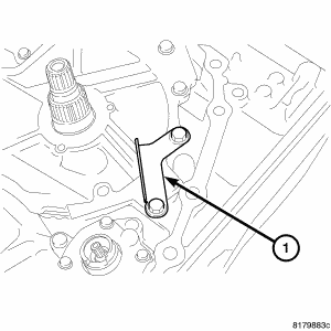
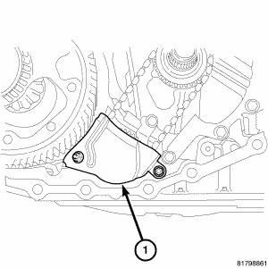
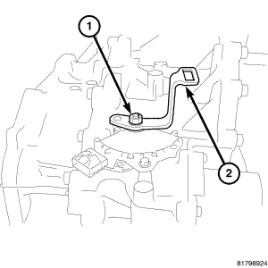
- Install the detent spring (1) onto the transaxle case. Install the bolt to hold the detent spring to the transaxle case and tighten the mounting bolt to 7 N.m (61 in.lbs.). See Fig 25.
 Courtesy of CHRYSLER LLC
- Install the outer race of the differential bearing (1) into the converter housing using Installer 9668 and Installer 4628 on 4WD, use Installer 4628 on 2WD and Handle C-4171. See Fig 26.
 Courtesy of CHRYSLER LLC
| 1 - PRELOAD SHIM |
| 2 - DIFFERENTIAL ASSEMBLY |
| 3 - TRANSAXLE CASE |
| 4 - CONVERTER HOUSING |
CAUTION:
When adjusting the preload, apply CVT fluid on the bearing to make it roll smoothly. When conducting measurements, measure two or more places and calculate the average value.
- Measure for the differential preload shim (1) in the following steps. Refer to the graphic as necessary when performing the steps. See Fig 27.
 Courtesy of CHRYSLER LLC
NOTE:
Gauge Bar 6311 can be used for doing the following measurement.
- The required differential preload is 0.17 to 0.29 mm (0.007 0.011 to in).
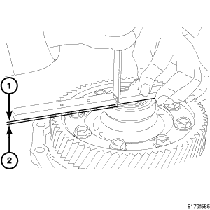
- Measure the distance (1-3) from the edge of the transaxle case to the select shim installation surface. This is differential measurement one.
 Courtesy of CHRYSLER LLC
NOTE:
Gauge Bar 6311 can be used for doing the following measurement.
- Install the differential assembly on the converter case and measure the distance (differential measurement two) (1-2) from the differential hub to the surface of the converter housing. See Fig 29.
 Courtesy of CHRYSLER LLC
NOTE:
Gauge Bar 6311 can be used for doing the following measurement.
- Install the outer race for the differential side bearing and measure the distance (differential measurement three) (1-2) from the differential case to the outer race of the differential side bearing. See Fig 30.
- The thickness of the required select shim is calculated as follows: differential measurement one, minus differential measurement two, plus differential measurement three, plus 0.23 mm (0.009 in).
 Courtesy of CHRYSLER LLC
CAUTION:
Do not re-use the select shim.
- Install the chosen select shim (1) into the transaxle case. See Fig 31.
 Courtesy of CHRYSLER LLC
- Install the outer race (1) of the differential bearing on the transaxle case using the Installer D-129 and Handle C-4171.
 Courtesy of CHRYSLER LLC
- Install the outer race (1) of the reduction gear bearing into the converter housing using Installer C-4628 and Handle C-4171. See Fig 33.
 Courtesy of CHRYSLER LLC
| 1 - REDUCTION GEAR |
| 2 - TRANSAXLE CASE |
| 3 - PRELOAD SHIM |
| 4 - BEARING OUTER RACE |
- The required preload on the reduction gear assembly is 0.13-0.19 mm (0.005-0.0075 in). Measure for the required preload shim (3) as follows: See Fig 34.
 Courtesy of CHRYSLER LLC
NOTE:
Gauge Bar 6311 can be used for doing the following measurement.
- Measure the distance (reduction assembly measurement one) (1-2) from the edge of the transaxle case to the select shim installation surface.
 Courtesy of CHRYSLER LLC
NOTE:
Gauge Bar 6311 can be used for doing the following measurement.
- Install the reduction gear assembly on the converter housing and measure the distance (reduction assembly measurement two) (1-2) from the top of the reduction gear assembly to the edge of the converter housing. See Fig 36.
 Courtesy of CHRYSLER LLC
CAUTION:
When adjusting the preload, apply CVT fluid on the bearing to make it roll smoothly. When conducting measurements, measure two or more places and calculate the average value.
NOTE:
Gauge Bar 6311 can be used for doing the following measurement.
- Install the outer race of the reduction gear bearing and measure the distance (reduction assembly measurement three) (1-2) from the top of the reduction gear assembly to the outer race of the reduction gear bearing. See Fig 37.
- The thickness of the required select shim is calculated as follows: reduction assembly measurement one, minus reduction assembly measurement two, plus reduction assembly measurement three, plus 0.16 mm (0.006 in).
 Courtesy of CHRYSLER LLC
CAUTION:
Do not re-use the select shim.
- Install the chosen select shim (1) into the transaxle case. See Fig 38.
 Courtesy of CHRYSLER LLC
- Install the outer race (1) of the reduction gear bearing on the transaxle case using Installer C-4628 and Handle C-4171. See Fig 39.
 Courtesy of CHRYSLER LLC
CAUTION:
Do not re-use the lip seal. Apply CVT fluid when installing the lip seal.
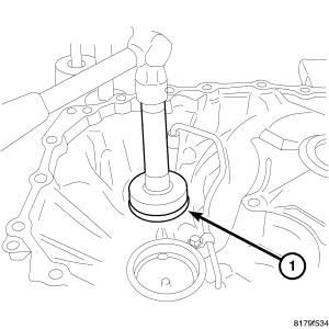
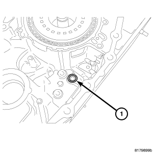
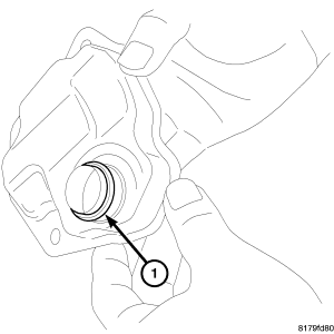
- Install the new lip seal (1) on the transaxle case. See Fig 40.
 Courtesy of CHRYSLER LLC
CAUTION:
Do not re-use the o-ring. Apply CVT fluid when installing the O-ring.
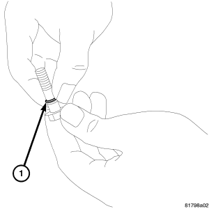
- Install the new o-ring (1) onto the oil pump mounting bolts. (Only for bolts installed from the outside of the transaxle case). See Fig 41.
 Courtesy of CHRYSLER LLC
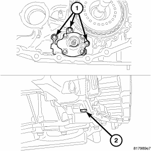
NOTE:
One of the oil pump retaining bolts is installed from the outside of the transaxle case in the rear part of the oil pump.
- Install the oil pump on the transaxle case. Install and tighten the mounting bolts (1) to 19 N.m (14 ft. lbs.) Install and tighten the mounting bolt (2) to 28 N.m (20 ft. lbs.). See Fig 42.
 Courtesy of CHRYSLER LLC
CAUTION:
Do not re-use the lip seal. Apply CVT fluid when installing the lip seal.
- Install the new lip seal (1) into the transaxle case. See Fig 43.
 Courtesy of CHRYSLER LLC
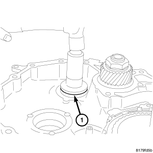
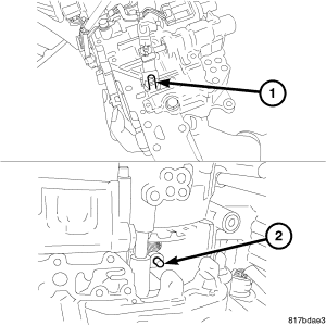
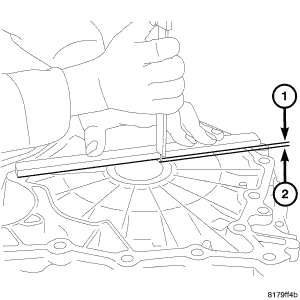
- Install the manual shaft (1) into the case.
- Install the pin at the manual shaft using a punch (2).
- To install the valve body assembly on to the transaxle case, insert a 75 mm (3 in.) long 3 mm (0.118 in.) wide rod or wire into the linkage stopper hole of the valve body assembly to set the pulley ratio linkage (1) in position. See Fig 44.
 Courtesy of CHRYSLER LLC
- Position the locating tab (1) of the terminal body and install the terminal body into the transaxle case. See Fig 45.
 Courtesy of CHRYSLER LLC
- Install the valve body assembly (1) up from the bottom side and install it into the transaxle case. See Fig 46.
 Courtesy of CHRYSLER LLC
- Align the notch (1) of the pulley ratio linkage with the sheave position sensor (2). See Fig 47.
 Courtesy of CHRYSLER LLC
CAUTION:
Apply CVT fluid when installing the bushing.
- Install the bushing (1) into the valve body assembly. See Fig 48.
 Courtesy of CHRYSLER LLC
- Tighten the mounting bolts of the valve body assembly to 8 N.m (70 in. lbs).
 Courtesy of CHRYSLER LLC
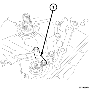
- Install the manual lever (1) onto the manual shaft. Install and tighten the mounting nut to 22 N.m 194 in. lb. See Fig 50.
 Courtesy of CHRYSLER LLC
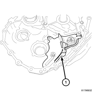
- Install the bracket (1) onto the valve body assembly. Install and tighten the mounting bolts to 8 N.m (70 in. lbs.). See Fig 51.
 Courtesy of CHRYSLER LLC
CAUTION:
Do not re-use the o-ring. Apply CVT fluid when installing the o-ring.
- Install the new o-ring (1) onto the new oil strainer. See Fig 52.
 Courtesy of CHRYSLER LLC
- Install the new oil strainer (1) onto the valve body assembly. Install and tighten the mounting bolts to 8 N.m (70 in. bs.). See Fig 53.
 Courtesy of CHRYSLER LLC
CAUTION:
Do not re-use the oil pan gasket. Remove any moisture, oil, and used gasket material from the surface where the new gasket is to be installed. When installing the oil pan gasket, align the dowel pin with the dowel pin hole in the oil pan gasket.
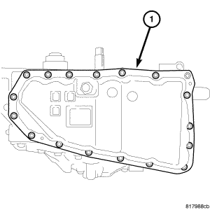
- Install the oil pan gasket (1) onto the transaxle case. See Fig 54.
 Courtesy of CHRYSLER LLC
CAUTION:
When installing the oil pan, align the dowel pin of the transaxle case with the dowel pin hole of the oil pan.
- Install the oil pan on the transaxle case (1). See Fig 55. Install and tighten the mounting bolts to 8 N.m (70 in. lbs.).
 Courtesy of CHRYSLER LLC
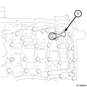
- Install the snap ring (1) onto the terminal body. See Fig 56.
 Courtesy of CHRYSLER LLC
CAUTION:
Do not re-use the seal rings. Apply Vaseline or assembly lube when installing the seal rings.
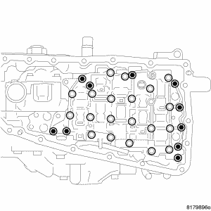
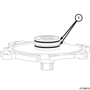
- Install the new seal rings (1) onto the reaction shaft support. See Fig 57.
 Courtesy of CHRYSLER LLC
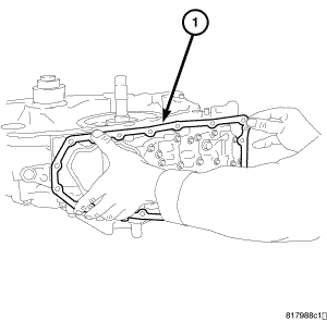
- Install the reaction shaft support (1) onto the transaxle case temporarily with the mounting bolts. See Fig 58.
 Courtesy of CHRYSLER LLC
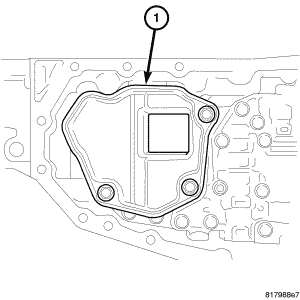
- Install the baffle plate (1) temporarily with the mounting bolts. See Fig 59.
 Courtesy of CHRYSLER LLC
- Install the baffle plate (1). See Fig 60. Install and tighten the mounting bolts to 6 N.m (52 in. lbs.).
 Courtesy of CHRYSLER LLC
- Install the bracket (1) as shown in illustration. Tighten the mounting bolts of the oil pump cover, baffle plate, and brackets to 26 N.m (19 in. lbs.). See Fig 61.
 Courtesy of CHRYSLER LLC
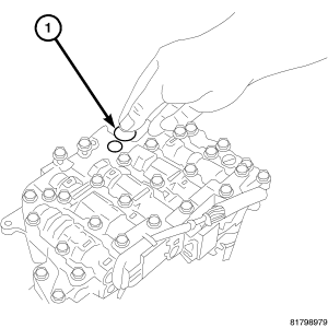
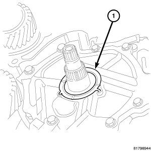
- Install the snap ring (1) into the oil pump. See Fig 62.
 Courtesy of CHRYSLER LLC
CAUTION:
Be sure to align the pawl of the thrust washer with the alignment hole of the oil pump cover. Apply Vaseline or assembly lube when installing the thrust washer.
- Install the thrust washer (1) onto the oil pump cover. See Fig 63.
 Courtesy of CHRYSLER LLC
CAUTION:
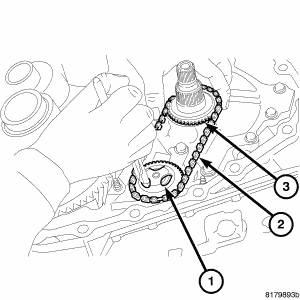
When necessary to replace any of the driven sprocket, oil pump chain, or drive sprocket, replace all components as a matched set. Pull the driven sprocket up softly and check that the driven sprocket is securely installed.
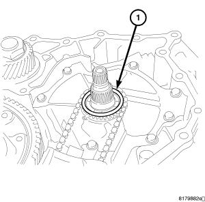
- Expand the snap ring (1).
- Install the driven sprocket, oil pump chain (2) and drive sprocket (3).
 Courtesy of CHRYSLER LLC
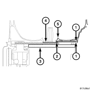
- The required clearance for the oil pump drive sprocket is 0.10-0.23 mm (0.004-0.009 in.). Measure the clearance (1) between the oil pump drive sprocket (4) and the converter housing (5) in the following procedure: See Fig 65.
 Courtesy of CHRYSLER LLC
NOTE:
Gauge Bar 6311 can be used for doing the following measurement.
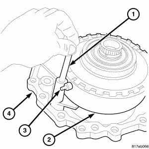
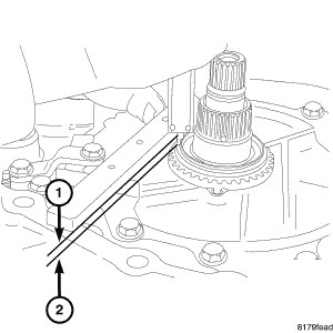
- Measure the distance (1-2) from the edge of the transaxle case to the select shim installation surface of the drive sprocket. This is the oil pump drive sprocket measurement one. See Fig 66.
 Courtesy of CHRYSLER LLC
NOTE:
Gauge Bar 6311 can be used for doing the following measurement.
- Measure the distance (1-2) from the edge of the converter housing to the surface touching the select shim contact surface. This is the oil pump drive sprocket measurement two. See Fig 67.
- Calculate the thickness of the required select shim with the following formula: The select shim is equal to the oil pump drive sprocket measurement one, plus the oil pump drive sprocket measurement two, minus 0.16 mm (0.0065 in.).
 Courtesy of CHRYSLER LLC
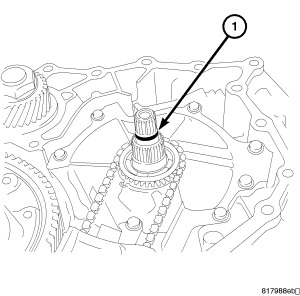
- Install the chosen select shim (1) onto the drive sprocket. See Fig 68.
 Courtesy of CHRYSLER LLC
- Install the baffle plate (1) over the oil pump driven sprocket. Install and tighten the mounting nut to 6 N.m (52 in. lbs.). See Fig 69.
 Courtesy of CHRYSLER LLC
CAUTION:
Do not re-use the o-ring. Apply CVT fluid when installing the o-ring.
- Install the new o-ring (1) onto the input shaft. See Fig 70.
 Courtesy of CHRYSLER LLC
- Install the differential assembly (1) into the transaxle case. See Fig 71.
 Courtesy of CHRYSLER LLC
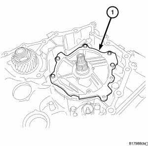
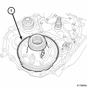
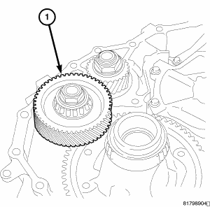
- Install the reduction gear assembly (1) into the transaxle case. See Fig 72.
 Courtesy of CHRYSLER LLC
CAUTION:
Do not re-use the converter housing oil seal (1). Apply CVT fluid when installing the converter housing oil seal (1).
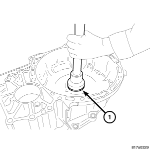
- Install the converter housing oil seal (1) into the converter housing with Installer 9858. See Fig 73.
 Courtesy of CHRYSLER LLC
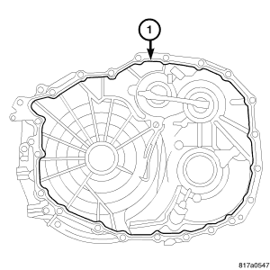
- Apply MOPAR gasket sealer (1) on the converter housing installation surface of the transaxle case. See Fig 74.
CAUTION:
Remove moisture, oil, and used sealant from the sealant application surface. Make sure that the starting point and the ending point are between two bolt holes.
 Courtesy of CHRYSLER LLC
- Install the converter housing on the transaxle case and tighten the bolts to 45 N.m (33 ft. lbs.).
 Courtesy of CHRYSLER LLC
- Install the transmission range sensor (TRS) (1) over the manual shaft and onto the transaxle case. See Fig 76.
 Courtesy of CHRYSLER LLC
CAUTION:
Do not re-use the TRS transmission range sensor.
- Put the manual shaft in the N position (3). See Fig 77. Install Park Neutral Switch Adjustment Tool 9876 (2) and adjust the position of the TRS (1).
 Courtesy of CHRYSLER LLC
- Install and tighten the mounting bolts of the TRS to 6 N.m (49 in. lbs.).
- Remove the TRS alignment tool from the TRS.
 Courtesy of CHRYSLER LLC
- Install the shift lever (1) onto the manual shaft. Install and tighten the mounting nut to 17 N.m (150 in. lbs.). See Fig 79.
 Courtesy of CHRYSLER LLC
CAUTION:
Do not re-use the o-ring. Apply CVT fluid when installing the o-ring.
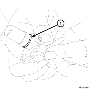
- Install the o-ring (1) onto the input speed sensor. See Fig 80.
 Courtesy of CHRYSLER LLC
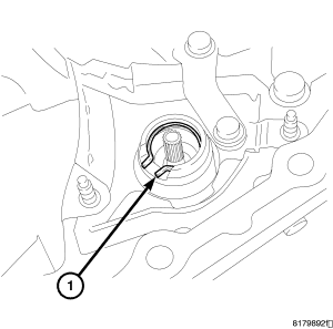
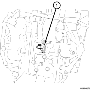
- Install the input speed sensor (1) into the transaxle case. Install and tighten the mounting bolt to 6 N.m (52 in. lbs.). See Fig 81.
 Courtesy of CHRYSLER LLC
CAUTION:
Do not re-use the o-ring. Apply CVT fluid when installing the o-ring.
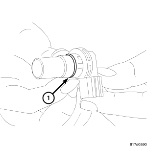
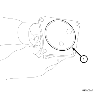
- Install the new o-ring (1) onto the output speed sensor. See Fig 82.
 Courtesy of CHRYSLER LLC
CAUTION:
Be sure to install the select shim between the secondary speed sensor and the converter housing before installing the secondary speed sensor.
- Install the output speed sensor (1) into the converter housing. Install and tighten the mounting bolt to 6 N.m (52 in lbs.). See Fig 83.
 Courtesy of CHRYSLER LLC
CAUTION:
Apply CVT fluid on the seal part when installing the CVT fluid filter.
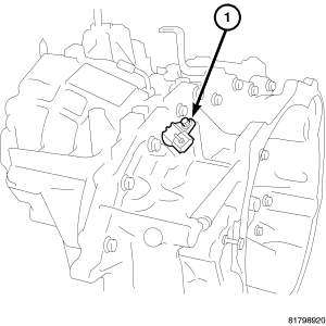
- Install the CVT fluid filter (1) into the transaxle case. See Fig 84.
 Courtesy of CHRYSLER LLC
CAUTION:
Do not re-use the o-ring. Apply CVT fluid when installing the o-ring.
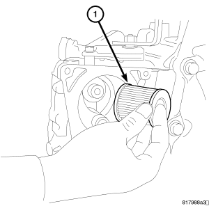
- Install the new o-ring (1) onto the CVT fluid filter.
 Courtesy of CHRYSLER LLC
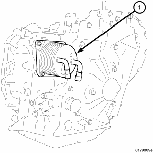
- Install the CVT fluid cooler (1) onto the transaxle case. Install and tighten the mounting bolts to 4 N.m (37 in.lbs.). See Fig 86.
 Courtesy of CHRYSLER LLC
- Remove the Transmission Service Stand 9878 (1) from the Belt side of the transmission case.
 Courtesy of CHRYSLER LLC
NOTE:
Gauge Bar 6311 can be used for doing the following measurement.
NOTE:
When conducting measurements, measure two or more places and calculate the average value.
- Install the torque converter on the transaxle and measure the dimension (1) to see if it is at least 13 mm. If the measurement is less than 13 mm, the torque converter is not fully installed. See Fig 88.
NOTE:
Use the designated brand of CVT fluid. Use of other brands of CVT fluid other than the designated brand will deteriorate the driveability and the durability of the CVT, and will cause damage to the CVT.
- Fill the transaxle with CVT fluid. See STANDARD PROCEDURE .