DTC P0622: Generator Field Not Switching Properly: Testing
- Turn ignition on. Using scan tool, actuate generator field driver circuit. Using a test light connected to ground, backprobe generator field driver circuit (Dark Green wire) on generator field connector terminal No. 2. See Fig 1
. If test light blinks, go to next step. If test light does not blink, go to step 3
.
- Wiggle wiring harness from generator to Powertrain Control Module (PCM). PCM is located in right rear of engine compartment. Using scan tool, read Diagnostic Trouble Codes (DTC) with actuator test still running. If generator field driver circuit DTC sets, repair wiring harness as necessary where wiggling caused problem to appear. Perform CHARGING SYSTEM TEST
under VERIFICATION TESTS. If DTC does not set, test is complete.
- Record all DTCs and clear codes. Check all charging system related connectors for loose, corroded or damaged terminals. Repair as necessary. Using scan tool, actuate generator field driver circuit. Using a voltmeter, measure voltage between ground and generator 2-pin connector field source terminal No. 1 (White/Red wire). If voltage is more than 10 volts, go to next step. If voltage is 10 volts or less, repair open in generator field source circuit between generator and PCM. Perform CHARGING SYSTEM TEST
under VERIFICATION TESTS.
- Turn ignition off. Disconnect PCM harness connectors. Disconnect field harness connector on rear of generator. Using an ohmmeter, measure resistance between PCM connector C2 terminal No. 10 generator field driver circuit (Dark Green wire) and ground. See Fig 1
and Fig 2
. If resistance is 100 ohms or more, go to next step. If resistance is less than 100 ohms, repair short to ground on Dark Green wire. Perform CHARGING SYSTEM TEST
under VERIFICATION TESTS.
- Measure resistance of Dark Green wire between PCM connector C2 terminal No. 10 and generator 2-pin connector terminal No. 2. If resistance is less than 5 ohms, go to next step. If resistance is 5 ohms or more, repair open generator field driver circuit. Perform CHARGING SYSTEM TEST
under VERIFICATION TESTS.
- Using an ohmmeter, measure resistance between generator field terminals on generator. If resistance is less than 0.5 ohm, replace generator. Perform CHARGING SYSTEM TEST
under VERIFICATION TESTS. If resistance is 0.5 ohm or more, go to next step.
- Using an ohmmeter, measure resistance between generator field terminals on generator. If resistance is more than 15 ohms, replace generator. Perform CHARGING SYSTEM TEST
under VERIFICATION TESTS. If resistance is 15 ohms or less, go to next step.
- If there are no other possible causes, replace PCM. Perform TEST VER-2
under VERIFICATION TESTS.
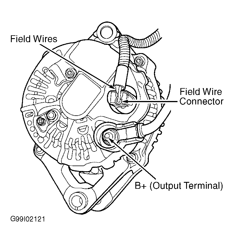 Courtesy of CHRYSLER CORP.
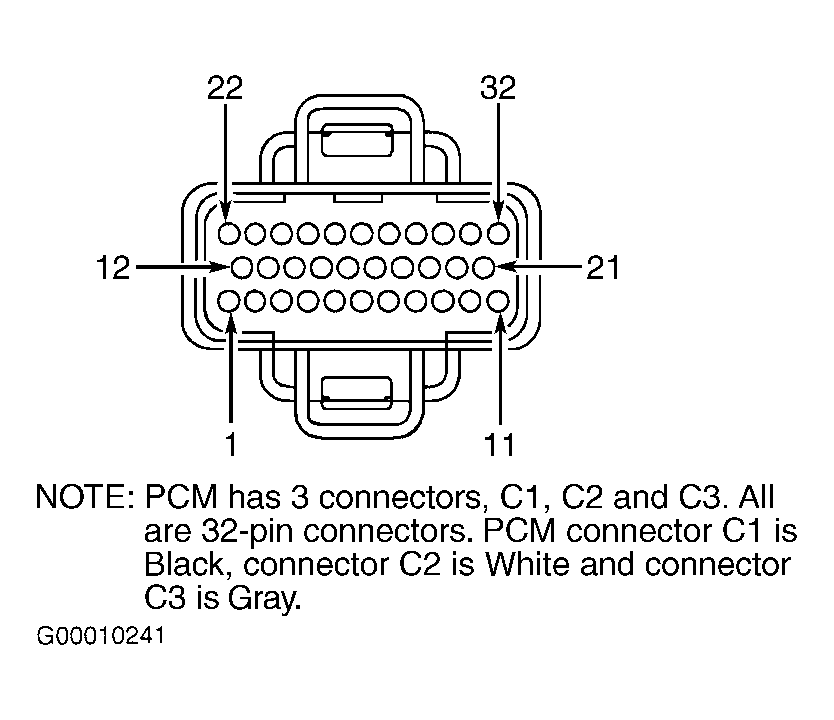 Courtesy of DAIMLERCHRYSLER CORPORATION