Headlight Sw Open Ckt
- Disconnect left multifunction switch connector. Turn ignition on. Connect a jumper wire between left multifunction switch connector terminals No. 4 (White/Dark Green wire) and No. 11 (Yellow wire). See Fig 1
. Using scan tool, select SENSORS under BODY. Read HEADLIGHT SW VOLTS. If scan tool does not display zero volts, go to next step. If scan tool displays zero volts, replace left multifunction switch. See appropriate
STEERING COLUMN SWITCHES article. Perform BODY VERIFICATION TEST
under VERIFICATION TESTS.
- Remove jumper wire. Turn ignition off. Disconnect Body Control Module (BCM) C1 connector. See Figure
. Using DVOM, measure resistance of Yellow wire between left multifunction switch connector terminal No. 11 and BCM C1 connector terminal No. 2. See Figure
and Fig 1
. If resistance is less than 5 ohms, go to next step. If resistance is 5 ohms or greater, repair open in Yellow wire. Perform BODY VERIFICATION TEST
under VERIFICATION TESTS.
- Using DVOM, measure resistance of White/Dark Green wire between left multifunction switch connector terminal No. 4 and BCM C1 connector terminal No. 16. If resistance is less than 5 ohms, go to next step. If resistance is 5 ohms or greater, repair open in White/Dark Green wire. Perform BODY VERIFICATION TEST
under VERIFICATION TESTS.
- Replace BCM. See BODY CONTROL MODULE
under REMOVAL & INSTALLATION. Perform BODY VERIFICATION TEST
under VERIFICATION TESTS.
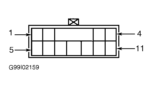 Courtesy of CHRYSLER CORP.