All Windows Inoperative
- Check circuit breaker No. 2, located in junction block. Junction block is mounted on right cowl side kick panel, below right end of instrument panel. See CIRCUIT BREAKER TEST
under TESTING. If circuit breaker tests as specified, go to next step. If circuit breaker does not test as specified, replace faulty circuit breaker.
- Remove right and left front door trim panels. See DOOR MODULE
under REMOVAL & INSTALLATION. Verify left and right 12-pin door module connectors are properly connected. If not properly connected, reseat connectors. If connectors are fully seated, go to next step.
- Disconnect 12-pin door module connectors (left and right). Using an ohmmeter, check for continuity between each connector ground terminal (Black wires) and chassis ground. See Fig 1
or Figure
. If no continuity exists, repair open Black wire to chassis ground. If continuity exists, go to next step.
- Using a voltmeter, check for battery voltage at door module connectors fused (B+) terminal (Tan wire). See Fig 1
or Figure
. If battery voltage does not exist, repair open Tan wire. If battery voltage exists, see BODY CONTROL COMPUTER
article.
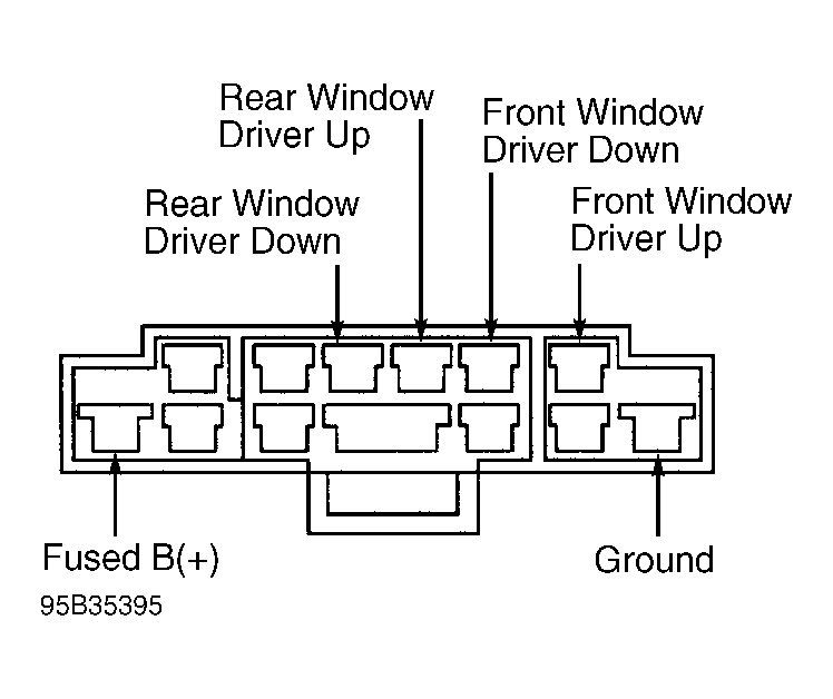 Courtesy of CHRYSLER CORP.
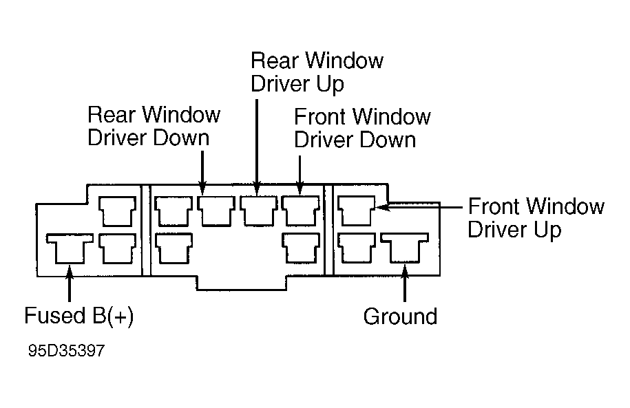 Courtesy of CHRYSLER CORP.