Installation, Mark 10 All Models
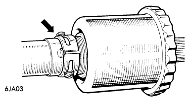
- Ensure front wheels are in straight ahead position. Feed outer column through bottom mounting bracket and secure to top mounting bracket. Tighten clip securing upper column to lower mounting. Turn inner column and centralize the turn signal switch striker between two arms on signal switch (see Fig 1).
 Courtesy of JAGUAR LAND ROVER NORTH AMERICA, LLC
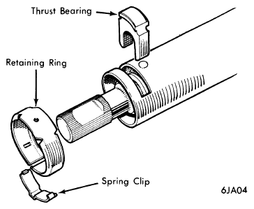
- Engage splines of inner column with internal splines of lower column. Replace thrust bearing and retaining clamp on bottom end of upper column section, then fit a new spring clip and tighten securely by pinching raised portion (see Fig 2).
 Courtesy of JAGUAR LAND ROVER NORTH AMERICA, LLC
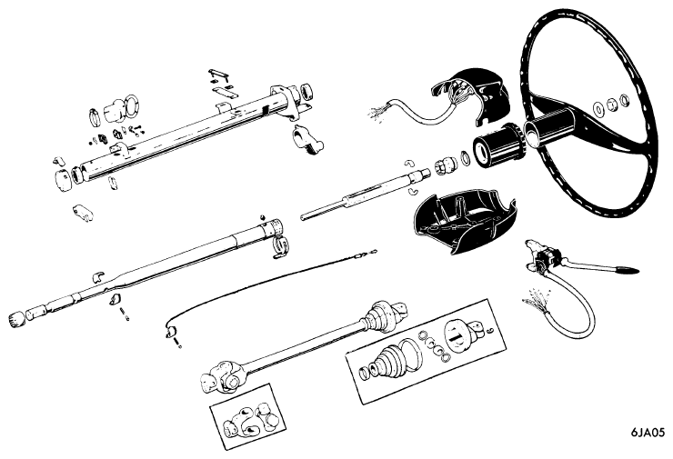
- Depress upper half of top universal joint fully and raise 1/4" (6 mm). Replace pinch bolt. Reconnect turn signal switch wiring. If vehicle is equipped with overdrive transmission, reconnect the overdrive switch.
 Courtesy of JAGUAR LAND ROVER NORTH AMERICA, LLC
- On automatic transmission equipped vehicles, reconnect wiring to neutral safety switch, then reconnect gear selector control cable ball joint.
- Replace steering column lock wiring (if equipped). Reinsert warning light bulb holders and replace upper switch cover to steering column. Connect horn switch wire to slip ring contact. Position and attach parcel tray as removed, then replace console and instrument panel.
- Place split cone into groove on steering shaft with tapered end toward top. Replace steering wheel with two holes on wheel center boss toward top. Torque retaining nut and lock nut. Secure horn ring, check position of horn contact rod, then position horn ring contact cover and insert retaining screws.