- Install new bearing onto input shaft assembly using bearing installer and press. Ensure outer race snap ring groove is toward front. Select appropriate snap ring to allow minimum axial play. See INPUT SHAFT SNAP RING IDENTIFICATION
table. Install new snap ring.
- Install 4th blocker ring. Using feeler gauge, measure clearance between synchronizer ring back and gear spline end. Clearance should be .030-.065" (.76-1.65 mm). Check braking effect of synchronizer ring by turning ring in one direction while pushing it toward gear cone. Ensure ring locks. If ring does not lock, replace synchronizer ring. Install needle bearing.
- Apply gear oil onto all moving surfaces of mainshaft and gear components. Using feeler gauge, measure clearance between synchronizer ring and gear spline end. See Fig 1
. See SYNCHRONIZER RING CLEARANCE
table.
INPUT SHAFT SNAP RING IDENTIFICATION
| Snap Ring ID |
Thickness - In. (mm) |
| A |
.083-.085 (2.10-2.15) |
| B |
.085-.087 (2.15-2.20) |
| C |
.087-.089 (2.20-2.25) |
| D |
.089-.091 (2.25-2.30) |
| E |
.091-.093 (2.30-2.35) |
| F |
.093-.095 (2.35-2.40) |
| G |
.095-.097 (2.40-2.45) |
SYNCHRONIZER RING CLEARANCE
| Synchro Assembly |
In. (mm) |
| 1st |
.032-.063 (.80-1.60) |
| 2nd |
.026-.069 (.65-1.75) |
| 3rd |
.030-.065 (.75-1.65) |
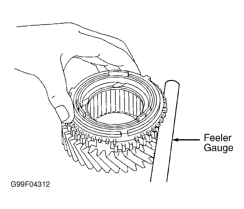 Courtesy of ISUZU MOTOR CO.
- Check braking effect of synchronizer ring by turning ring in one direction while pushing it toward gear cone. Ensure ring locks. If ring does not lock, replace synchronizer ring.
- Inspect 1st-2nd shift arm. Measure center groove of shift arm with caliper. Dimension should be .208" (5.28 mm). Measure flange around gear face of reverse gear and calculate clearance between reverse gear and shift arm. Reverse gear flange thickness should be .197" (5.0 mm). Clearance between gear and arm should be .006-.016" (.15-.41 mm).
- Inspect 3rd-4th shift arm. Measure center groove of shift arm with caliper. Dimension should be .402" (10.2 mm). Measure tip of shift arm thickness, and calculate clearance between hub sleeve No. 2 and shift arm. Clearance should be .006-.014" (.15-.35 mm).
- Inspect clutch hub and hub sleeve. Check for any signs of wear or damage, and replace parts if needed. Install hub sleeve onto clutch hub and ensure it slides smoothly. Using dial indicator, measure mainshaft gears inside diameter. See MAINSHAFT GEAR INSIDE DIAMETERS
table. If diameter exceeds specification, replace gear(s).
- Inspect mainshaft. Using micrometer, measure outer diameter of mainshaft journals. See MAINSHAFT JOURNAL DIAMETERS
table. See Fig 2
. Using micrometer, measure mainshaft flange thickness. Thickness should be .197" (5.0 mm). Using dial indicator (with mainshaft set in "V" blocks), measure mainshaft runout in center. Runout should be less than .0006" (.015 mm). If runout exceeds specification, replace mainshaft.
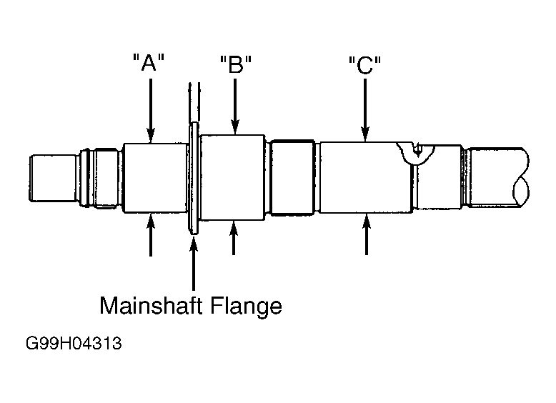 Courtesy of ISUZU MOTOR CO.
- Install 3rd gear by installing needle bearing, gear and block ring onto mainshaft. Install clutch hub No. 2 and sleeve, with tapered edge of hub toward front. Using screwdriver, install 2 springs and 3 inserts, positioning key springs so end gaps are not in line with each other. Use press to seat hub sleeve No. 2. Ensure synchronizer ring key is aligned and gear rotates smoothly. Select appropriate snap ring to provide minimum axial play. See 3RD GEAR SNAP RING SPECIFICATIONS
table. After installing new snap ring, use feeler gauge to check 3rd gear thrust clearance. Clearance should be .004-.010" (.10-.25 mm).
- Install 2nd gear by installing needle bearing and 2nd gear block ring set to mainshaft.
- Install 3 inserts and 3 springs onto clutch hub No. 1. Install clutch hub No. 1 onto reverse gear, checking installed direction so gear flange is toward front. Using press, install hub No. 1 and reverse gear onto mainshaft. Ensure projection of inner ring aligns with hub No. 1 slots, and gear rotates smoothly. Select appropriate snap ring to provide minimum axial play. See HUB NO. 1 SNAP RING SPECIFICATIONS
table. After installing snap ring, ensure gear rotates smoothly. Measure 2nd gear thrust clearance with dial indicator. Clearance should be .004-.010" (.10-.25 mm).
MAINSHAFT GEAR INSIDE DIAMETERS
| Gear |
In. (mm) |
| 1st |
1.8116-1.8126 (46.015-46.040) |
| 2nd |
2.0872-2.0882 (53.015-53.040) |
| 3rd |
1.7329-1.7339 (44.015-44.040) |
MAINSHAFT JOURNAL DIAMETERS
| Journal |
In. (mm) |
| A |
1.4954-1.4961 (37.984-38.000) |
| B |
1.8498-1.8504 (46.984-47.000) |
| C |
1.5346-1.5352 (38.979-38.995) |
3RD GEAR SNAP RING SPECIFICATIONS
| Snap Ring ID |
Thickness - In. (mm) |
| A |
.071-.073 (1.80-1.85) |
| B |
.073-.075 (1.85-1.90) |
| C |
.075-.077 (1.90-1.95) |
| D |
.077-.079 (1.95-2.00) |
| E |
.079-.081 (2.00-2.05) |
| F |
.081-.083 (2.05-2.10) |
| G |
.083-.085 (2.10-2.15) |
HUB NO. 1 SNAP RING SPECIFICATIONS
| Snap Ring ID |
Thickness - In. (mm) |
| A |
.091-.093 (2.30-2.35) |
| B |
.093-.095 (2.35-2.40) |
| C |
.095-.097 (2.40-2.45) |
| D |
.097-.098 (2.45-2.50) |
| E |
.098-.100 (2.50-2.55) |
| F |
.100-.102 (2.55-2.60) |
| G |
.102-.104 (2.60-2.65) |
- Install 1st gear bearing spacer, 1st gear needle bearing, synchronizer assembly, and 1st gear onto mainshaft. See Fig 3
. Align projection of inner ring with hub No. 1 slots. Ensure gear rotates smoothly. Install 1st gear thrust washer pin and thrust washer onto mainshaft. Align straight pin with thrust washer slot.
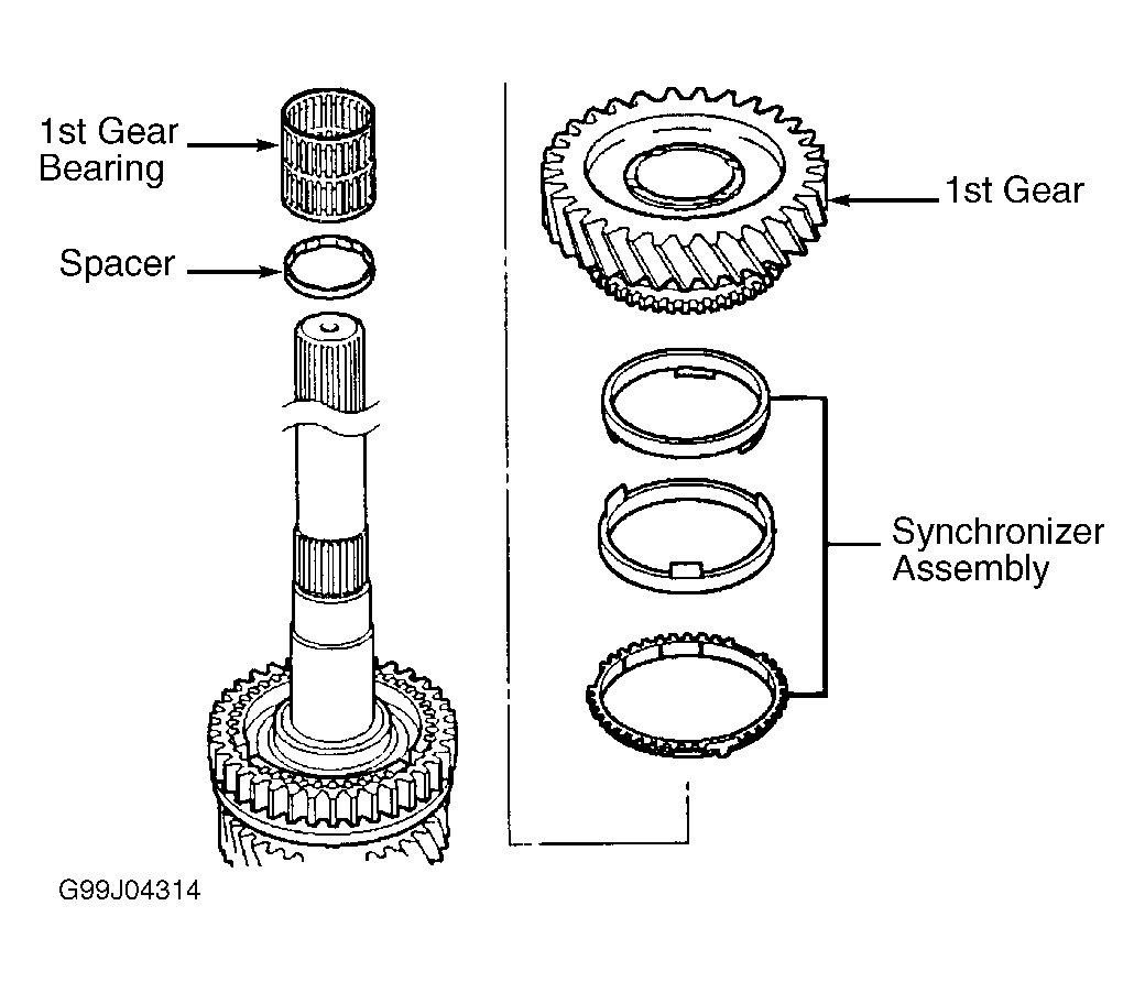 Courtesy of ISUZU MOTOR CO.
- Using installer and press, install mainshaft center bearing, with snap ring groove toward rear of mainshaft. Using feeler gauge, measure 1st gear thrust clearance. Clearance should be .004-.018" (.10-.45 mm).
- Using installer and press, install 5th gear onto mainshaft. Select appropriate snap ring to allow minimum axial play. See 5TH GEAR SNAP RING SPECIFICATIONS
table. After snap ring is in place, mount mainshaft assembly vertically into soft-jaw vise. Measure radial clearance of 1st, 2nd and 3rd gears. See MAINSHAFT GEAR RADIAL CLEARANCE
table under TRANSMISSION DISASSEMBLY. See Fig 4
.
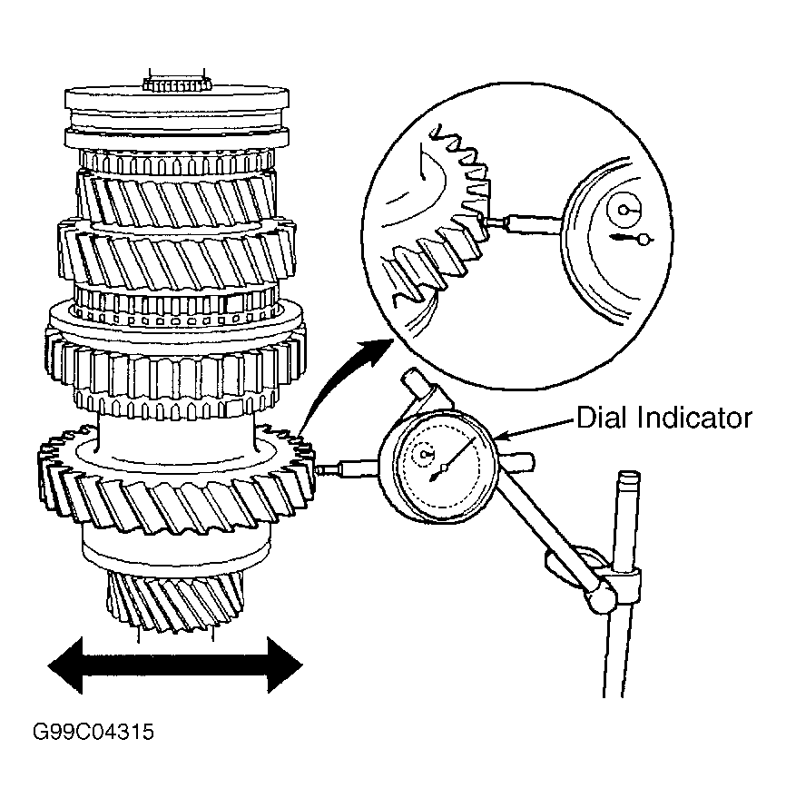 Courtesy of ISUZU MOTOR CO.
- Press counter gear front bearing onto counter gear shaft. Select appropriate snap ring to provide minimum axial play. See COUNTER GEAR BEARING SNAP RING SPECIFICATIONS
table. Install snap ring.
5TH GEAR SNAP RING SPECIFICATIONS
| Snap Ring ID |
Thickness - In. (mm) |
| C |
.108-.110 (2.75-2.80) |
| D |
.110-.112 (2.80-2.85) |
| E |
.112-.114 (2.85-2.90) |
| F |
.114-.116 (2.90-2.95) |
| G |
.116-.118 (2.95-3.00) |
| H |
.118-.120 (3.00-3.05) |
| J |
.120-.122 (3.05-3.10) |
| K |
.122-.124 (3.10-3.15) |
| L |
.124-.126 (3.15-3.20) |
| M |
.126-.128 (3.20-3.25) |
| N |
.128-.130 (3.25-3.30) |
| P |
.130-.132 (3.30-3.35) |
COUNTER GEAR BEARING SNAP RING SPECIFICATIONS
| Snap Ring ID |
Thickness - In. (mm). |
| A |
.079-.081 (2.00-2.05) |
| B |
.081-.083 (2.05-2.10) |
| C |
.083-.085 (2.10-2.15) |
| D |
.085-.087 (2.15-2.20) |
| E |
.087-.089 (2.20-2.25) |
| F |
.089-.091 (2.25-2.30) |
- Install NEW oil seal into front cover. Drive in seal to .44-.48" (11.2-12.2 mm) in from front cover surface. Install transfer adapter oil seal. Drive seal in to .411-.450" (10.45-11.45 mm) in from transfer adapter surface.
- Install oil receiver pipe. Install reverse restrict pin into transfer case adapter. Drive slotted spring pin into side of transfer case adapter, below shift control box opening. Clean plug hole threads, and apply thread lock compound onto plug threads. Install plug into transfer adapter, and tighten to specification. See TORQUE SPECIFICATIONS
.
- Using Torx-head wrench, install and tighten plug into top of transfer case adapter. Using hex-head wrench, install and tighten plug into side of transfer case adapter, just below shift control box opening. Mount intermediate plate into soft-jawed vise. Install reverse shift arm bracket. Tighten bolts to specification. See TORQUE SPECIFICATIONS
. Install reverse shift arm No. 2 onto shift arm No. 1. Install new "E" ring. Install reverse shift arm No. 2 onto reverse shift arm bracket.
- Install reverse shift arm No. 1 compression spring and ball onto reverse shift arm No. 1. Install reverse shift rod from rear side of intermediate plate, pushing ball in with screwdriver. Install reverse shift arm No. 1 lock ball onto reverse shift arm. Install interlock pin into intermediate plate. Insert 5th-reverse shift rod from front side of intermediate plate. Install 2 new shift rod snap rings onto 5th-reverse shift rod and reverse shift rod.
- Install 1st-2nd interlock pin into intermediate plate. Insert 1st-2nd shift rod from rear of intermediate plate. Install 3rd-4th shift rod interlock pin into intermediate plate. Insert 3rd-4th shift rod from rear of intermediate plate. Install new 1st-2nd and 3rd-4th shift rod snap rings.
- Install 3 shift detent balls and springs into side of intermediate plate. Clean plug holes, apply thread lock compound onto plugs and install all 4 plugs into side of interlock plate.
- Coat all mainshaft assembly parts with clean gear oil. Tap 5th-reverse shift rod rearward to Reverse position. Install shift arm No. 1 and No. 2 onto mainshaft. Tap intermediate plate while installing mainshaft assembly through shift arms No. 1 and No. 2, engaging shift rods into proper holes. Install large snap ring onto mainshaft gear on front side of intermediate plate. Tap 5th-reverse shift rod into Neutral position with plastic hammer.
- Align projection of hub No. 2 with synchronizer ring slots, and install input shaft assembly onto mainshaft. Ensure input shaft rotates smoothly after installation. Temporarily install counter gear shaft into intermediate plate. Drive in center bearing with bearing race snap ring groove toward rear. Tapping on rear of counter gear shaft will aid in bearing installation.
- Install reverse idler gear and shaft by inserting into intermediate plate with slot toward rear and into reverse shift arm No. 2. Align and install bearing plate. Tighten bolts to specification. See TORQUE SPECIFICATIONS
. Install 5th gear thrust washer pin and thrust washer onto counter gear shaft.
- Install 3 inserts and reverse block ring, and install 3 compression springs onto block ring, pushing inserts inward and downward to seat. Install synchronizer outer ring, cone ring and pull ring into reverse block ring. Turn pull ring to 30 degrees from tangs on synchronizer ring. Install hub sleeve No. 3 and reverse block ring set onto counter 5th gear. Ensure flat side of synchronizer ring is forward.
- Install counter 5th gear bearing, counter 5th gear and reverse block ring set onto counter gear shaft, through 5th-reverse shift arm and onto 5th-reverse shift rod. Install 5th gear spline piece. Ensure gear rotates smoothly.
- Using feeler gauge, measure counter 5th gear thrust clearance. Clearance should be .004-.014" (.10-.35 mm). Select appropriate snap ring to provide minimum axial play. See COUNTER 5TH GEAR SNAP RING SPECIFICATIONS
table. Install snap ring.
COUNTER 5TH GEAR SNAP RING SPECIFICATIONS
| Snap Ring ID |
Thickness - In. (mm) |
| A |
.110-.112 (2.80-2.85) |
| B |
.112-.114 (2.85-2.90) |
| C |
.114-.116 (2.90-2.95) |
| D |
.116-.118 (2.95-3.00) |
| E |
.118-.120 (3.00-3.05) |
| F |
.120-.122 (3.05-3.10) |
| G |
.122-.124 (3.10-3.15) |
- Install and tighten 2 shift arm bolts to specification. See TORQUE SPECIFICATIONS
. Using pin punch, drive in slotted pin into shift arm.
- Thoroughly clean transmission case mounting surface. Apply liquid gasket around mounting surface and inside mounting holes. Stand transmission on wooden blocks and tap transmission case into position with plastic hammer. Install front bearing shaft snap ring and counter gear shaft bearing snap ring. Install front cover. Apply thread locking compound onto bolt threads. Install 8 front cover mounting bolts. Tighten to specification. See TORQUE SPECIFICATIONS
. Ensure input shaft and mainshaft rotate smoothly.
- Thoroughly clean transfer adapter case mounting surface. Apply liquid gasket around mounting surface, inside bolt holes. Using plastic hammer, tap transfer adapter case into position with transmission case. Install and tighten 10 mounting bolts. Tighten bolts in even pattern. Install wire clamp under appropriate mounting bolt.
- Align project on shift control housing into shift rod groove and install shift lever shaft. Drive in slotted spring pin into hole near control box opening. Apply thread compound onto plug thread and install plug into end of transfer adapter, above output shaft. Tighten to specification. See TORQUE SPECIFICATIONS
.
- Using NEW gasket, install gear control box onto top of transfer case adapter. Install clutch housing and tighten all bolts evenly to specification. See TORQUE SPECIFICATIONS
. Install NEW gaskets and tighten 1st-2nd switch, 3rd-4th switch and back-up light switches.
- Apply grease onto clutch release push rod, bearing hub, fork split pin hole and spline surface of top gear shaft. Install clutch shift fork. Install split pin. Install release bearing onto shift fork. Install drain plug and fill plug with NEW gaskets.