Lock Actuator Circuit
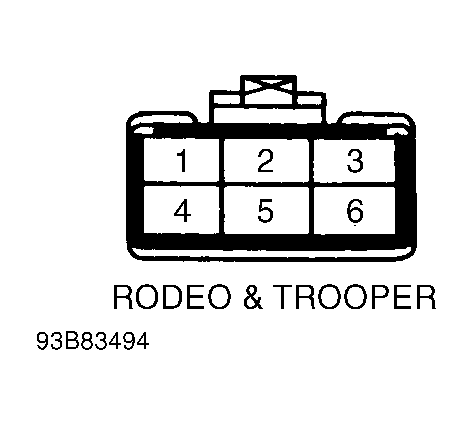
- Disconnect control unit connector (located behind right side kick panel). Apply battery voltage to connector terminal No. 4 and ground to terminal No. 5. SeeFig 1
. Doors should unlock.
- Apply battery voltage to connector terminal No. 5 and ground to terminal No. 4. Doors should lock. If any one actuator does not operate, perform LOCK ACTUATOR TEST
. If actuator is okay, check door harness. If all actuators are inoperative, check control unit harness connector.
 Courtesy of ISUZU MOTOR CO.