Power Window Switch Circuit (Passenger Side & Rear)
- Remove power window switch from door trim panel. Disconnect power window switch harness connectors. Using an ohmmeter, check continuity between power window switch connector terminals No. 1 and 5. SeeFig 1
. Continuity should exist. Check continuity between power window switch connector terminal No. 2 and ground, with appropriate power window switch at driver's side power window switch in OFF position. Continuity should exist.
- Using a DVOM, check voltage between power window switch connector terminal No. 2 and ground, with ignition switch in ON position, and appropriate power window switch at driver's side power window switch in OFF position, then in DOWN position. Voltage should not be present with switch in OFF position. Battery voltage should be present with switch in DOWN position.
- Using a DVOM, check voltage between power window switch connector terminal No. 3 and ground, with ignition switch in ON position, and lock switch in ON position, then in OFF position. Voltage should not be present with switch in ON position. Battery voltage should be present with switch in OFF position.
- Check continuity between power window switch connector terminal No. 4 and ground, with appropriate power window switch at driver's side power window switch in OFF position. Continuity should exist.
- Using a DVOM, check voltage between power window switch connector terminal No. 4 and ground, with ignition switch in ON position, and appropriate power window switch at driver's side power window switch in OFF position, then in UP position. Voltage should not be present with switch in OFF position. Battery voltage should be present with switch in UP position.
- If continuity or voltage is not as specified in any of the previous steps, repair appropriate circuit as necessary. If all circuits are okay, check, repair or replace appropriate component(s) as necessary.
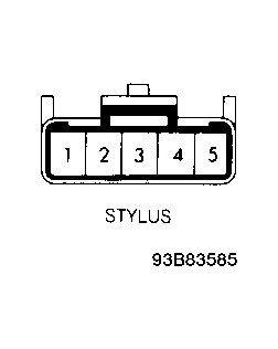 Courtesy of ISUZU MOTOR CO.