HOLLEY BREAKERLESS Ignition: Overhaul: Distributor: Reassembly
- Install new Teflon bushings in bores of advance weights, new Teflon thrust washers on advance weight pins and advance weights on pins. Install new advance springs and ensure weights pivot freely on pins. On models without tachometer drive, lubricate distributor shaft with engine oil and install shaft into distributor using care not to damage governor housing seals (if equipped).
- On models with tachometer drive, place tachometer drive gear in housing with hub of gear facing downward and lubricate distributor shaft with engine oil. Install shaft into distributor using care not to damage governor housing seals (if equipped).
- Start shaft into bore of tachometer drive and align roll pin hole in gear with hole in shaft (if original shaft and gear are being installed). Support housing and press shaft into tachometer gear until roll pin holes are aligned. If new shaft and gear are being installed, gear must be installed 4.58" from top of housing to top of gear with the shaft held to the bottom of housing.
- Install new gear-to-housing thrust washer (if used) on shaft. Start gear or thrust collar on distributor shaft and align roll pin holes (if original components are being reinstalled). Support distributor housing in a press and press gear or thrust collar onto shaft until pin holes align (original components) or until specified end play is obtained (new components). Measure end play clearance between gear or thrust washer and lower end of distributor housing. If distributor has gear-to-housing thrust washer, check end play between gear or thrust collar and thrust washer.
- On models reusing original shaft and gear, install driven gear or thrust collar roll pin. On models using new shaft and gear, support distributor in drill press and use roll pin hole in gear as guide to drill hole in distributor shaft. Install roll pin. If unit is equipped with tachometer drive, rotate shaft and check for interference.
- If clearance is satisfactory at upper and lower limits of shaft, install tachometer drive gear roll pin on units using original components. On units using new components check clearance, support distributor in drill press, use roll pin hole in tachometer drive gear as guide, drill hole in distributor shaft and install roll pin.
- Ensure mechanical advance components are correctly installed on distributor shaft. Using distributor cam lubricant, lubricate trigger wheel assembly pilot surface of shaft. Grooves in pilot diameter must be filled and plate surface between grooves should have a thin film of lubricant. Reservoir in center should be filled to depth of plate surface.
- Install new slider blocks on trigger wheel and position wheel assembly on pilot surface of distributor shaft. Align slider block flats with advance flyweight slots and push wheel into position. Install retainer and remove excess lubricant. Saturate felt wick using engine oil, squeeze excess from wick and install in top bore of wheel assembly. Mechanical advance should operate freely.
- Use bearing lubricant on tachometer drive gear, driven gear and drive shaft bushings. Install driven gear and shaft into distributor housing and install driven gear shaft plug. Fill drive gear cavity in housing with lubricant. Install tachometer drive cover plate with a new gasket and tighten screws.
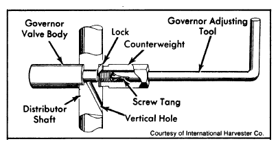
- On models equipped with governor valve proceed as follows: Install 7/16" deep well socket, governor counterweight and lock on Governor Adjuster (SE-2072-1). Engage counterweight in socket. Position slotted end of adjuster through horizontal hole in distributor shaft from the side nearest vertical hole of shaft.
- Install valve body on slotted end of adjuster and engage tang of adjusting screw into slot in end of adjuster. Push body and counterweight together (toward center of shaft) and screw counterweight into valve body while holding adjuster stationary. Tighten counterweight and bend lock tabs.
 Courtesy of NOT AVAILABLE
- Preset governor valve by turning adjuster clockwise until spring screw is bottomed. Back screw out approximately 3 1/2 turns. Install valve adjusting plug and tighten using an Allen wrench. Install clamp and gasket assembly, seal wire, and governor air inlet filter.
- Install 3 thrust buttons in upper sensor plate and lubricate buttons with distributor cam lubricant. Install upper plate to lower plate and install retaining spring. Position sensor to upper plate, install mounting screw loosely, and engage wiring clip into hole in plate. Install sensor plate assembly to distributor and install mounting screws. Tighten screws alternately and evenly.
- Position sensor wiring seal/retainer into slot of distributor housing, position vacuum diaphragm assembly to housing and install mounting screws. Connect vacuum diaphragm rod to pin on sensor plate assembly and install retaining ring. Adjust trigger wheel-to-sensor air gap to 0.008" and tighten sensor mounting screw.