Motor Home Chassis: Reassembly
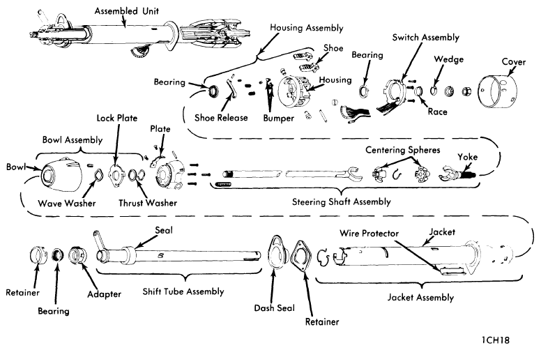
- When lubrication is called for, use lithium soap grease. Install dash panel seal, mounting plate and instrument panel seal on column. On column shift models, press a new shift lever spring into shift lever housing. Slide shift lever housing over upper end of column. Place wave washer and lock plate in position. Work lock plate into notches by tipping plate toward housing (compressing wave washer) at open side of column. Lubricate lock plate and upper end of shift tube.
- Carefully install shift tube into lower end of column (make sure foam seal is at lower end of shift tube). Align keyway in tube with key in shift lever housing and complete installation of shift tube using suitable installer tool. Shift lever housing key must bottom in shift tube slot to be fully installed. Remove installer tool from column. Lubricate and push foam seal in flush with column housing.
CAUTION:
Do not hammer or force tube when installing in column.
- Pull up on shift lever housing (to compress wave washer) and install thrust washer and retaining ring. Be sure ring is seated in both slots of shift tube. Lubricate inside diameter of bearing housing support and install support, aligning bolt holes in support with bolt holes in lock plate. Install four support screws and tighten.
- Assemble steering shaft as follows: Lubricate and assemble centering spheres and preload spring. Install spheres into upper (short) shaft and rotate 90°. Install lower 90° to upper shaft and over centering spheres. Slowly straighten shafts while compressing preload spring.
 Courtesy of NOT AVAILABLE
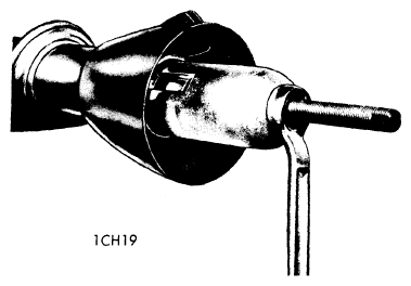
- Install shaft assembly into housing from upper end. Install lower bearing and adapter, bearing reinforcement, wire clip, pot joint coupling and lower shaft as follows: Press new bearing into adapter and install lower bearing and adapter onto lower end of steering shaft. Place in position in lower end of column, aligning wide tab of adapter with open slot in column. Place lower bearing reinforcement over end of column (open position of reinforcement to open slot in column) and install clip. Make sure all three tabs of clip are fully engaged with slots in reinforcement and column.
 Courtesy of NOT AVAILABLE
- Assemble bearing housing as follows: Press new upper and lower bearing races into bearing housing. Lubricate and install bearings into races. Place lock shoe springs in position in housing. Install each shoe in place and compress spring until a suitable size straight punch can be used to hold shoes in position. Once shoes are in place, install retaining pin. Install shoe release lever and drive in pivot pin. Install tilt release lever. Lubricate shoes and release lever.
- Install bearing housing assembly to support. Hold tilt release lever up until shoes have fully engaged support. Lubricate and install bearing housing pivot pins. Press pins in flush with housing. Place housing in full "UP" position and then install tilt spring and retainer (tapered end of spring first). Push into housing approximately 3/16" and rotate counterclockwise 1/8 turn.
- Lubricate and install upper bearing upper race, race seat and lock nut. Tighten lock nut to remove lash and then further tighten 1/16 to 1/8 turn (column must be in straight-ahead position). Remove tilt release lever.
- Install directional signal switch. Install shift lever and pivot pin if column shift model. Install neutral-start or back-up lamp switch. Remove column from vise.
ADJUSTMENT SPECIFICATIONS
| Application |
Specifications |
| Shift Lever-to-Spacer Clearance |
.005" |
TIGHTENING SPECIFICATIONS
| Applications |
Ft.Lbs. |
| 1000-1300 (1966-70) |
| |
Flexible Coupling Bolt |
15-20 |
| Lower Joint Clamp Bolt |
| |
|
3/8-16 (Pot Type Coupling) |
30-35 |
| 7/16-14 (Pot Type Coupling) |
45-50 |
| 7/16-14 (Universal Joint Type Coupling) |
50-55 |
| |
Lower Bearing Adapter Sleeve Bolts |
8-12 |
| Column Mounting Bracket-To-Pedal Mounting Bracket |
15-25 |
| Column Mounting Bracket-To-Column |
12-17 |
| Column-To-Dash Panel Clamp |
4-7 |
| 1010-1310, 100 & 200 (1971-74) |
| |
Fabric Coupling-To-Steering Gear Pinch Bolt |
30 |
| Fabric Coupling Nuts |
20 |
| Lower Joint Clamp Bolt |
| |
|
13/16" Dia. Shaft |
30 |
| 3/4" Dia. Shaft |
50 |
| Scout II |
| |
Steering Column-To-Mounting Bracket |
35-45 |
| Column Mounting Bracket-To-Pedal Mounting Bracket |
20 |
| Column-To-Dash Panel Mounting Clamp |
6-8 |
| Pot Type Coupling-To-Steering Gear |
35-45 |
| Application |
INCH Lbs. |
| 1000-1300 (1966-70) |
| |
Back-Up Light Switch Mounting Screws |
12-17 |
| Hazard Warning Switch Knob |
2-5 |
| Directional Signal Switch Mounting Screws |
30-40 |
| 1010-1300, 100 & 200 Models (1971-74) |
| |
Shift Gate Mounting Screws |
45 |
| Housing Screws |
60 |
| Directional Signal Switch Mounting Screws |
25 |
| Ignition Switch Mounting Screw |
35 |
| Steering Shaft Lock Cover Screw |
15 |
| Neutral-Start Switch Mounting Screws |
15 |
| Hazard Warning Switch Knob |
5 |
| Scout II |
| |
Ignition Switch Mounting Bolt |
30-40 |
| Directional Signal Switch Mounting Screw |
30-40 |
| Directional Signal Switch Housing Mounting Bolt |
70-80 |
COLUMN ALIGNMENT SPECIFICATIONS
| Application |
Angular Relationship |
| 1000-1300 (4x2) W/Power Steering |
3° ± 1/2° |
| 1300 (4x2) W/Manual Steering |
3° ± 1/2° |
| All Others |
1° ± 1° |