Diagnostic Procedure
- Turn ignition off. Inspect EVAP canister for cracks. See Fig 1. If problem is found, replace EVAP canister. If no problem is found and CONSULT-II is available, go to next step. If no problem is found and CONSULT-II is not available, go to step 3.
- Disconnect vacuum hose connected to EVAP-CPVCSV at EVAP service port. See Fig 2. Connect vacuum gauge to disconnected hose. Start engine and let it idle. Select PURG VOL CONT/V in ACTIVE TEST mode with CONSULT-II. Increase engine speed to 2000 RPM. Press "Qd" and "Qu" on CONSULT-II screen to adjust PURG VOL CONT/V opening. When opening is 100 percent, vacuum should exist. When opening is zero percent, vacuum should not exist. If vacuum is as specified, go to step 7. If vacuum is not as specified, go to step 4.
- Start engine and warm to normal operating temperature. Turn ignition off. Disconnect vacuum hose connected to EVAP-CPVCSV at EVAP service port. See Fig 2. Connect vacuum gauge to disconnected hose. Start engine and let it idle for at least 80 seconds. Check for vacuum while increasing engine speed to 2000 RPM. Vacuum should exist. Release throttle and let engine idle. Vacuum should not exist. If vacuum is as specified, go to step 7. If vacuum is not as specified, go to next step.
- Turn ignition off. Check EVAP purge line for improper connection or disconnection. See VACUUM DIAGRAMS
article. If no problem is found and CONSULT-II is available, go to step 6. If no problem is found and CONSULT-II is not available, go to next step. If problem is found, repair as necessary. After repair, repeat appropriate DTC confirmation procedure.
- Disconnect vacuum hoses at EVAP service port. Check hoses for cracks, kinks, clogging, blockage or tears. Check hoses by blowing through each hose. Also, check vacuum port at intake manifold. If no problem is found, go to step 7. If problem is found, repair as necessary. After repair, repeat appropriate DTC confirmation procedure.
- Start engine. Perform PURG VOL CONT/V in ACTIVE TEST mode with CONSULT-II. Engine speed should vary according to valve opening. If operation is as specified, go to step 8. If operation is not as specified, go to next step.
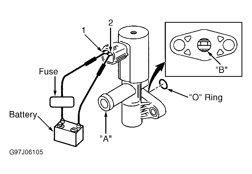
- Turn ignition off. Remove vacuum hoses from EVAP-CPVCSV. Connect an auxiliary length of hose to either port on valve. Using CONSULT-II in ACTIVE TEST mode, modulate EVAP-CPVCSV from zero-100 percent. When EVAP-CPVCSV is at 100 percent, air should flow between ports "A" and "B". When valve is at zero percent, air should not flow. Using generic scan tool, disconnect EVAP-CPVCSV 2-pin harness connector. Using jumper wires, apply battery voltage to EVAP-CPVCSV terminals. See Fig 4. Air should flow between ports "A" and "B". Remove jumper wires. Air should not flow. If operation is as specified, go to next step. If operation is not as specified, replace EVAP-CPVCSV. After repair, repeat appropriate DTC confirmation procedure.
- Check for disconnection or improper connection of hose connected to EVAP Control System Pressure Sensor (EVAP-CSPS). Pressure sensor is located under vehicle, mounted on EVAP canister. See Fig 1. If no problem is found, go to next step. If problem is found, repair as necessary. After repair, repeat appropriate DTC confirmation procedure.
- Disconnect EVAP-CSPS 2-pin harness connector. Check harness connectors for evidence of water damage or corrosion. If no damage exists, go to next step. If water damage or corrosion exists, replace EVAP-CSPS. After repair, repeat appropriate DTC confirmation procedure.
- Check EVAP-CSPS function by performing appropriate DTC CONFIRMATION TEST under DTC P0452 and DTC P0453. See DTC P0452 and DTC P0453
. If 1st trip DTC is not detected, go to next step. If 1st trip DTC is detected, replace EVAP-CSPS. After repair, repeat appropriate DTC confirmation procedure.
- Disconnect hose to EVAP-CVCV from EVAP canister. Check hose for blockage. If blockage is found, clean with compressed air. If blockage is not found, go to next step.
- Remove EVAP-CVCV. Check for rust in port "B". See Fig 5. If rust does not exist, go to next step. If rust exists, replace EVAP-CVCV. After repair, repeat appropriate DTC confirmation procedure.
- If using CONSULT-II, go to next step. If using generic scan tool, go to step 15.
- Reconnect all harness connectors. Turn ignition on. Perform VENT CONTROL/V in ACTIVE TEST mode with CONSULT-II. When VENT CONTROL/V is ON, air should not flow between ports "A" and "B". When VENT CONTROL/V is OFF, air should flow between ports "A" and "B". It should take less than one second for valve to open or close. If operation is as specified, go to step 16. If operation is not as specified, clean EVAP-CVCV with compressed air, and retest. If operation is still not as specified, replace EVAP-CVCV. After repair, repeat appropriate DTC confirmation procedure.
- Disconnect EVAP-CVCV 2-pin harness connector. Using jumper wires, apply battery voltage to EVAP-CVCV terminals. See Fig 5. Attempt to blow through valve. Air should not flow between ports "A" and "B". Remove jumper wires. Air should flow. It should take less than one second for valve to open or close. If operation is as specified, go to step 17. If operation is not as specified, clean EVAP-CVCV with compressed air, and retest. If operation is still not as specified, replace EVAP-CVCV. After repair, repeat appropriate DTC confirmation procedure.
- Install any disconnected parts. Connect vacuum hoses and harness connectors. Start engine and warm to normal operating temperature. Turn ignition off, and then on. Using CONSULT-II in DATA MONITOR mode, observe CLSD THL/P SW. Measurement must be made with TP switch installed. When throttle is closed, CLSD THL/P SW parameter should display ON. When throttle is open, CLSD THL/P SW parameter should display OFF. If CLSD THL/P SW parameter displays as specified, go to step 19. If parameter does not display as specified, go to step 18.
- Install any removed parts. Start engine and warm to normal operating temperature. Turn ignition off. Disconnect closed Throttle Position (TP) switch 3-pin harness connector. See Figure. Check continuity between closed TP switch terminals No. 5 and 6 (component side). Measurement must be made with TP switch installed. When throttle is closed, continuity should exist. When throttle is open, no continuity should exist. If closed TP sensor tests as specified, go to step 19. If sensor does not test as specified, go to next step.
- Check closed TP switch adjustment. See THROTTLE POSITION SENSOR, IGNITION TIMING & IDLE SPEED
in ON-VEHICLE ADJUSTMENTS article. If closed TP switch adjustment is as specified, go to next step. If TP switch adjustment is not as specified, repair as necessary. If closed TP switch can be adjusted, go to next step. If closed TP switch can not be adjusted, replace TP switch. After repair, repeat appropriate DTC confirmation procedure.
- Check for leaks in EVAP purge line. See VACUUM DIAGRAMS
article. If no leaks are found, clean EVAP purge line with compressed air and go to next step. If leaks are found, replace EVAP purge line. After repair, repeat appropriate DTC confirmation procedure.
- No problem is indicated at this time. Problem may be intermittent. See INTERMITTENTS
in TROUBLE SHOOTING - NO CODES article.
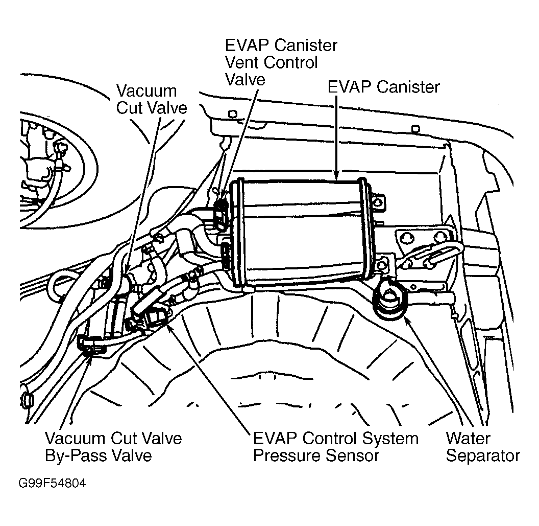 Courtesy of NISSAN MOTOR CO., U.S.A.
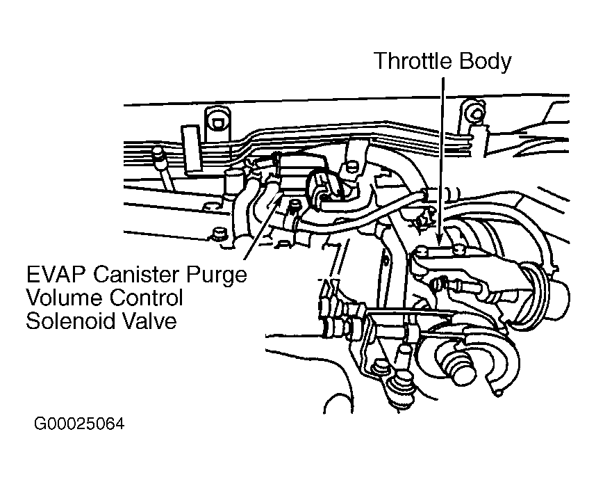 Courtesy of NISSAN MOTOR CO., U.S.A.
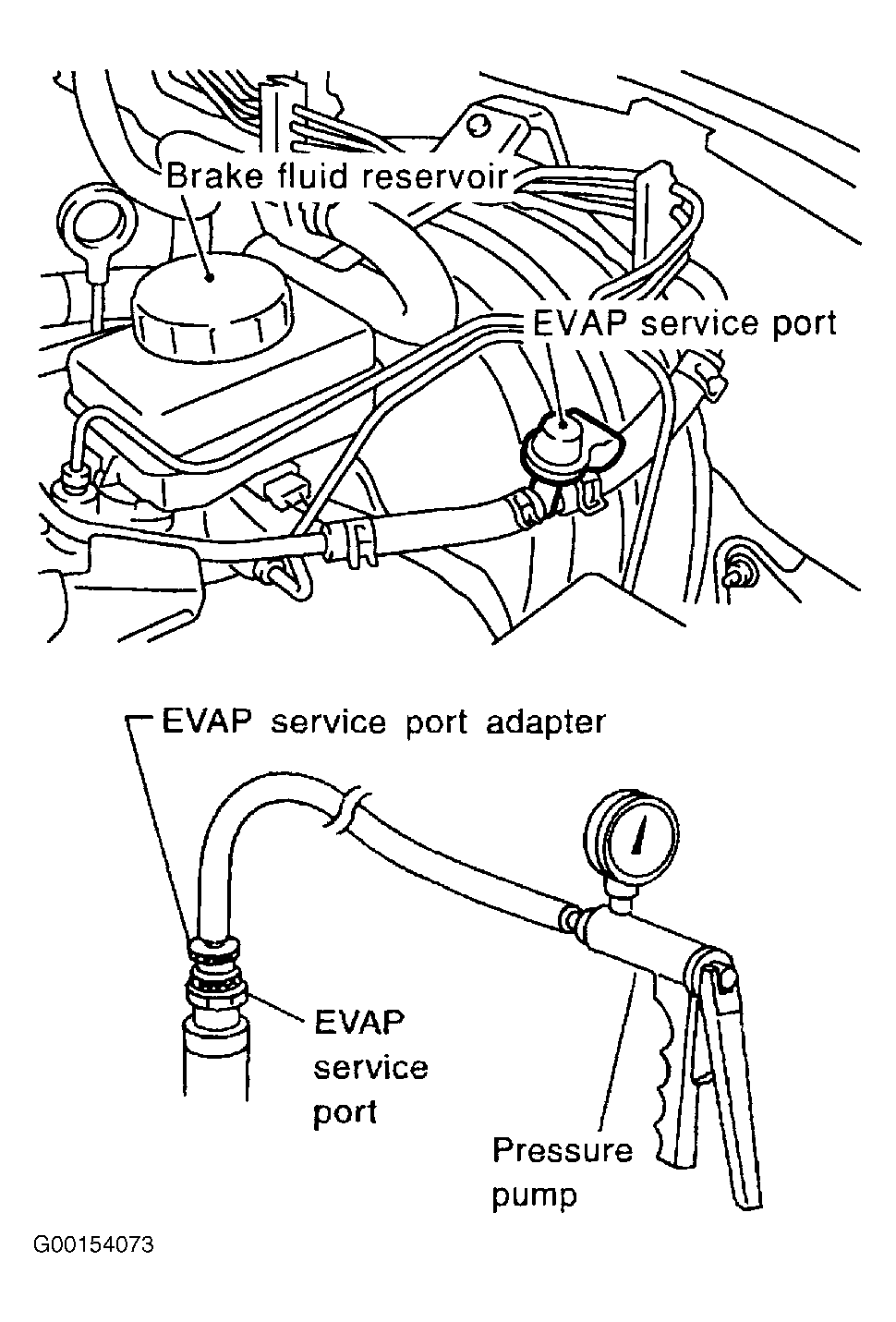 Courtesy of NISSAN MOTOR CO., U.S.A.
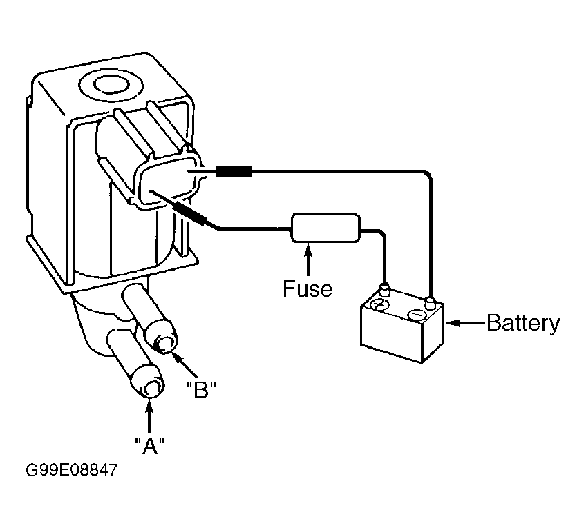 Courtesy of NISSAN MOTOR CO., U.S.A.
 Courtesy of NISSAN MOTOR CO., U.S.A.