- Apply grease to the lip of the drive shaft oil seal, and attach the casing.
CAUTION:
The drive shaft oil seal cannot be reused. Always replace after every disassembly.
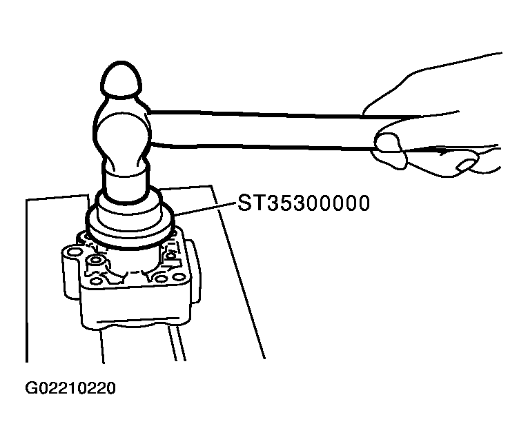 Courtesy of NISSAN MOTOR CO., U.S.A.
- When removing the dowel pin, if it is difficult to insert with your hands, insert into the casing by tapping lightly with a hammer or similar tool.
- Attach the flow control A valve, flow control valve spring, and the flow control B valve assembly to the locations indicated in the drawing left.
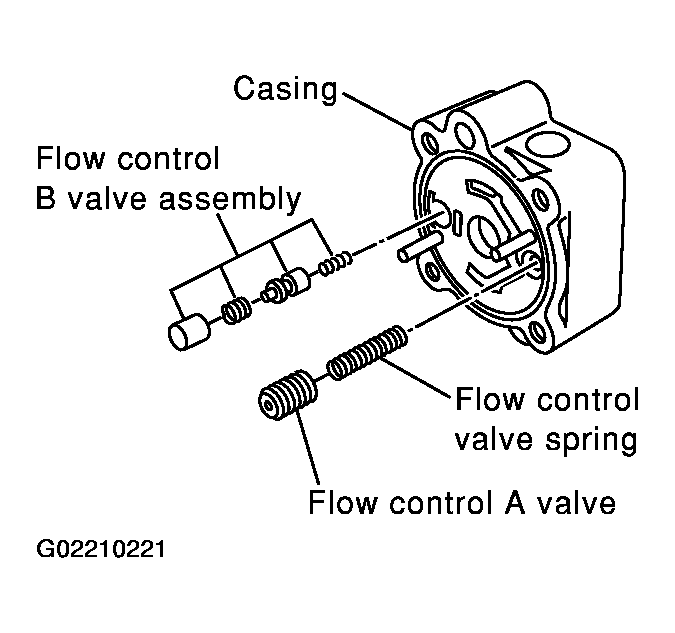 Courtesy of NISSAN MOTOR CO., U.S.A.
- Match the dowel pin A on the flow control A valve side with the notch B of the side plate (front), and attach the side plate (front) to the casing.
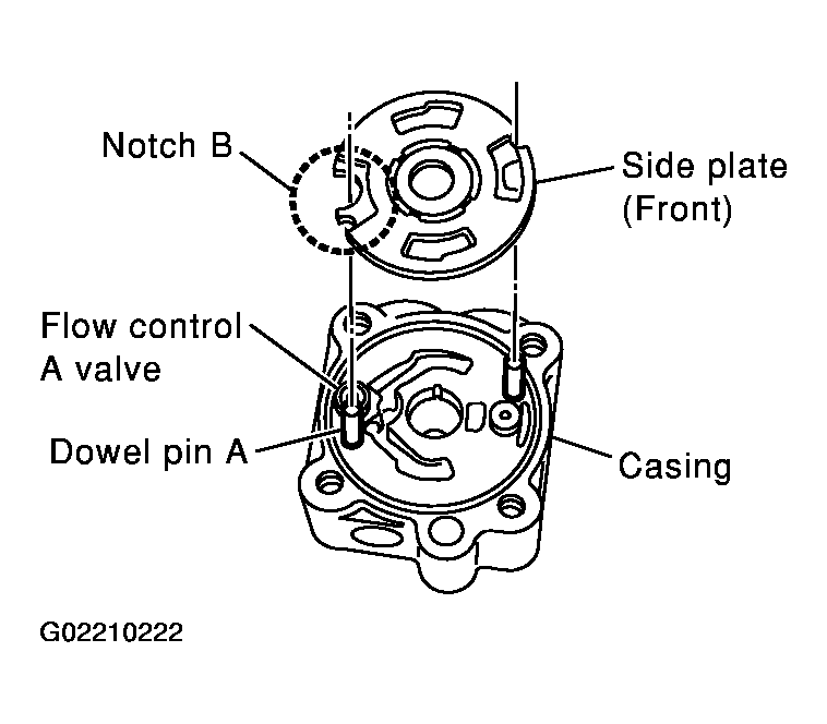 Courtesy of NISSAN MOTOR CO., U.S.A.
- Face the cam ring side with fewer pores towards the casing, and attach the cam ring on top of the side plate (front).
- Attach the pulley to the casing.
CAUTION:
Attach with care so as not to damage the drive shaft oil seal.
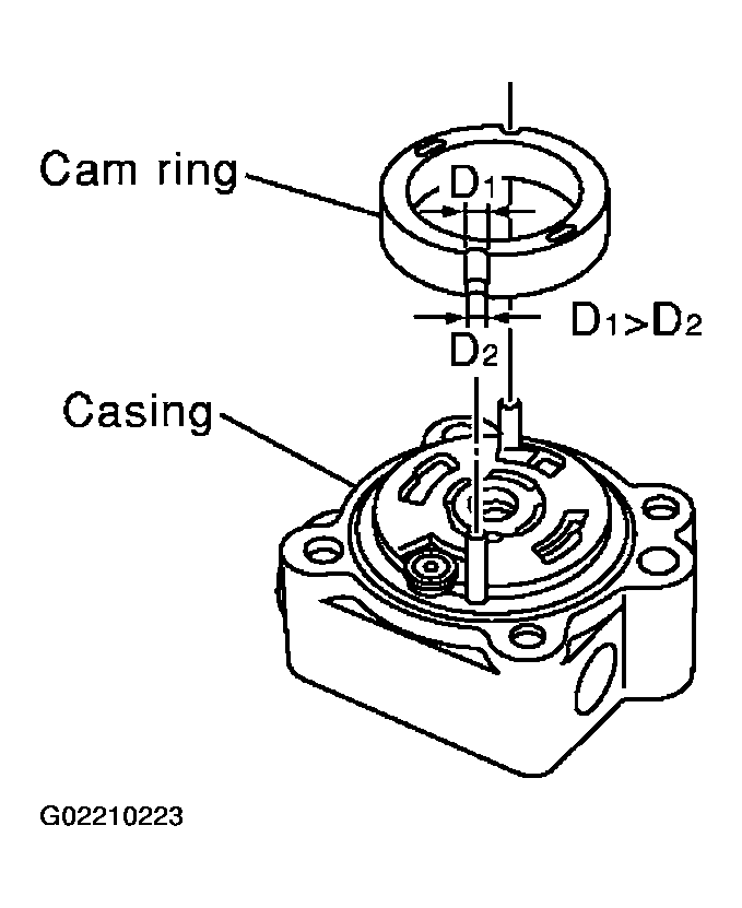 Courtesy of NISSAN MOTOR CO., U.S.A.
- Face the side of the rotor with the punch mark towards the casing, and attach the rotor to the drive shaft.
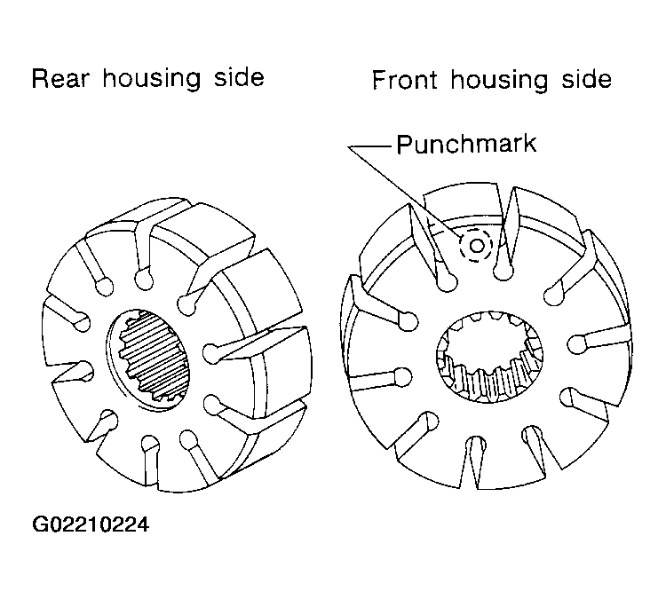 Courtesy of NISSAN MOTOR CO., U.S.A.
- Attach the vane to the rotor so that the vane's arc touches the cam ring.
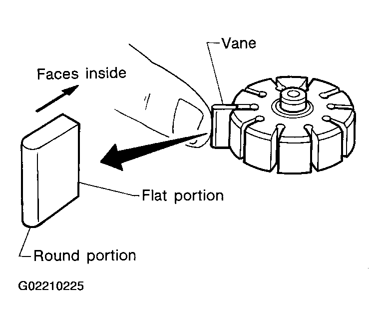 Courtesy of NISSAN MOTOR CO., U.S.A.
- Use a hammer or suitable tool to insert the rotor snap ring into the drive shaft channel.
CAUTION:
- The rotor snap ring cannot be reused. Always replace after every disassembly.
- Insert with care so as not to damage the rotor or the drive shaft.
- If the rotor is damaged, replace the power steering as an assembly.
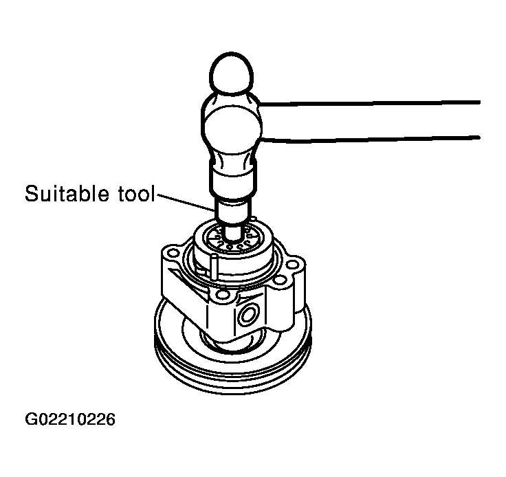 Courtesy of NISSAN MOTOR CO., U.S.A.
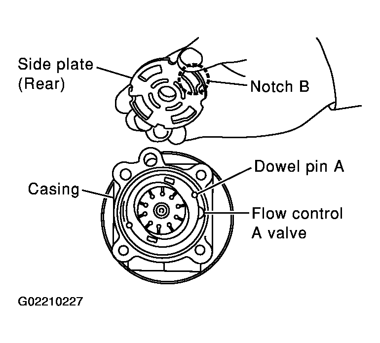
- Match the dowel pin A on the flow control A valve side with the notch B of the side plate (rear), and attach the side plate (rear) to the cam ring.
- Apply Genuine Nissan PSF II or equivalent to O-ring and attach to the casing.
CAUTION:
The O-ring cannot be reused. Always replace after every disassembly.
 Courtesy of NISSAN MOTOR CO., U.S.A.
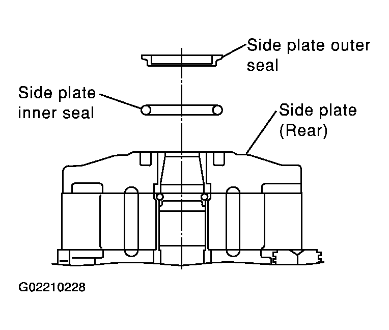
- Attach a side plate inner seal and side plate outer seal with Genuine Nissan PSF II or equivalent applied, to the side plate (rear).
CAUTION:
The side plate inner seal and outer seal cannot be reused. Always replace after every disassembly.
- Set the power steering pump on the vice.
CAUTION:
When securing to the vice, use an aluminum plate or other material to protect the installation surface of the power steering pump from damage.
- Attach the rear cover to the casing, and secure the bolts (4 bolts) in a diagonal order to the specified torque.
- Attach the front bracket to the casing, and secure the bolts (2 bolts) to the specified torque.
- Attach the suction pipe O-ring to the grooves of the suction pipe, and attach the suction pipe to the casing with attachment bolts.
CAUTION:
The suction pipe seal cannot be reused. Always replace after every disassembly.
 Courtesy of NISSAN MOTOR CO., U.S.A.