Front Door Key Cylinder Switch Check
- Check Door Key Cylinder Switch Input Signal (Lock/Unlock Signal)
Turn ignition off. Using DVOM, measure voltage (backprobe) between ground and terminals No. 41 (Yellow wire) or No. 30 (Light Green wire) at Smart Entrance Control Unit (SECU) harness connector. See Figure
. Ensure voltage is as specified. See DOOR KEY CYLINDER SWITCH VOLTAGE SPECIFICATIONS
table. If voltage is as specified, door key cylinder switch is okay. If voltage is not as specified, go to next step.DOOR KEY CYLINDER SWITCH VOLTAGE SPECIFICATIONS
| Terminal No. & Key Position |
Specification |
| 41 |
| Neutral/Unlock |
5 Volts |
| Lock |
Zero Volts |
| 30 |
| Neutral/Lock |
5 Volts |
| Unlock |
Zero Volts |
- Check Door Key Cylinder Switch
Disconnect door key cylinder switch harness connectors. Using DVOM, check for continuity between door key cylinder switch terminals. Ensure continuity is as specified. See DOOR KEY CYLINDER SWITCH CONTINUITY SPECIFICATIONS
table. If continuity is not as specified, replace faulty door key cylinder switch. If continuity is as specified, check for open or short circuit between appropriate door key cylinder switch and SECU. Check door key cylinder switch ground circuit. Repair as necessary.
DOOR KEY CYLINDER SWITCH CONTINUITY SPECIFICATIONS
| Application (Terminal No.) & Key Position |
Continuity |
| Left Side |
| (1 & 2) Neutral/Lock |
No |
| (2 & 3) Neutral/Unlock |
No |
| Right Side |
| (1 & 2) Lock |
Yes |
| (2 & 3) Unlock |
Yes |
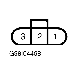 Courtesy of NISSAN MOTOR CO., U.S.A.