ABS/TCS No Code (TAC Module Power/Ground Circuit)
- Disconnect TAC module harness connector. Check terminals for damage or loose connections. Reconnect TAC module harness connector. Repeat ABS/TCS self-diagnostic procedure. While observing dash warning indicators, turn ignition on. If SLIP and TCS OFF indicator light illuminates during bulb check, system is okay. If SLIP and TCS OFF indicator light does not illuminate during bulb check, go to next step.
- Turn ignition off. Disconnect TAC module harness connector. Turn ignition on. Using a DVOM connected to ground, check for voltage at terminal No. 8 (Yellow wire). See Figure
. If battery voltage is present, go to next step. If battery voltage is not present, go to step 4
.
- Check for voltage at TAC module harness connector terminals No. 9 (Red wire) and No. 19 (Red wire). See Figure
. If battery voltage is present, go to step 5
. If battery voltage is not present, go to next step.
- Turn ignition off. Check fuses No. 28 (10-amp) and No. 30 (10-amp) located in fuse block. Replace fuses as necessary. Turn ignition on. If either fuse fails again, repair wiring harness between fuse panel and TAC module. See Fig 1
.
- Turn ignition off. Disconnect TAC module harness connector. Check for continuity between ground and TAC module harness connector terminals No. 10 (Black wire), No. 20 (Black wire) and No. 107 (Black wire). See Figure
. If continuity exists, replace TAC module. If continuity does not exist, repair appropriate wire(s).
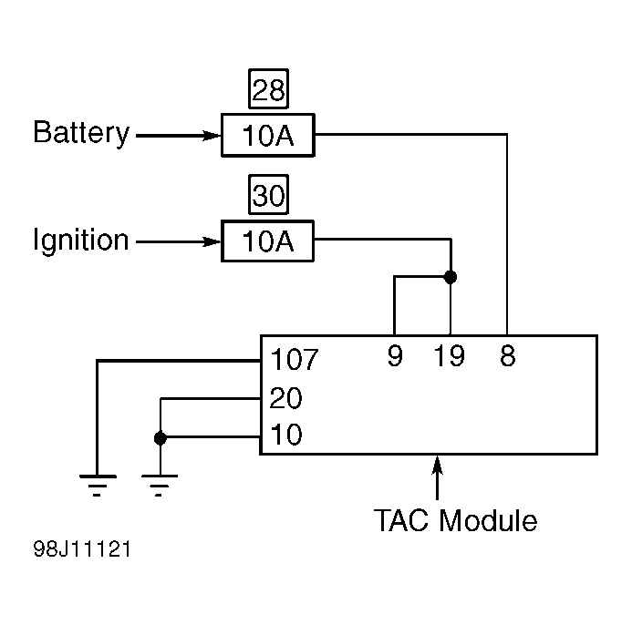 Courtesy of NISSAN MOTOR CO., U.S.A.