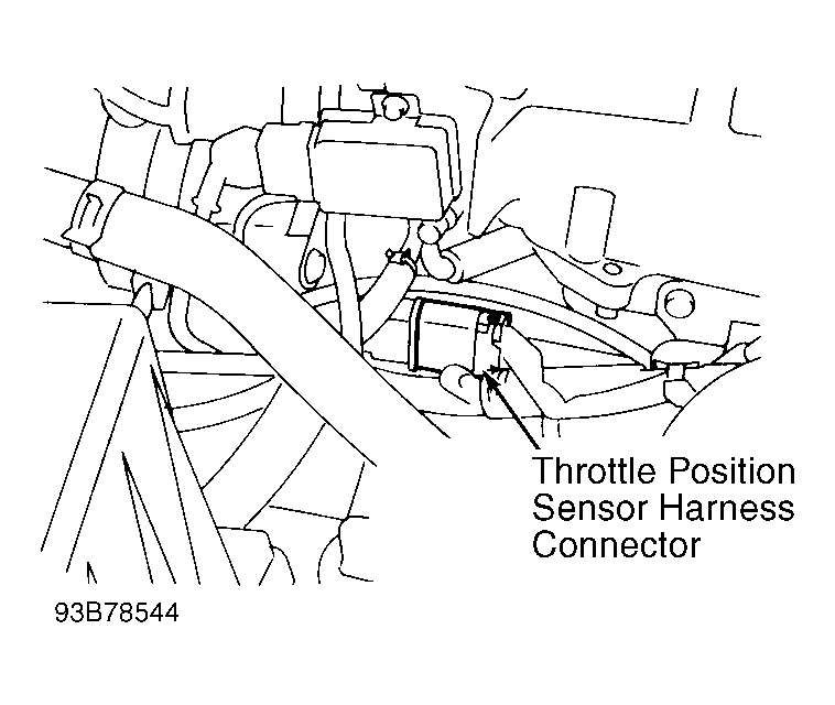
DTC 43: Throttle Position Sensor (TPS)
- Check Power Supply
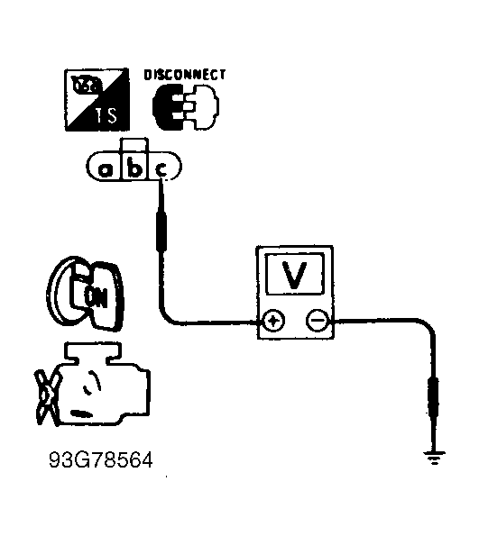
- Turn ignition off and disconnect TPS harness connector. Turn ignition on. Measure voltage between TPS connector terminal "c" (Green wire) and ground. See Fig 1
and Fig 2
. If voltage is approximately 5 volts, go to next step. If voltage is not as specified, repair harness or connectors as necessary.
 Courtesy of NISSAN MOTOR CO., U.S.A.
 Courtesy of NISSAN MOTOR CO., U.S.A.
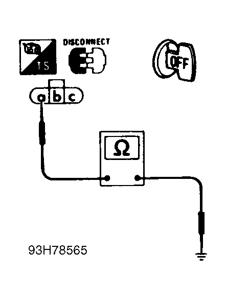
- Check Ground Circuit
- Turn ignition off. Verify harness continuity between TPS connector terminal "a" (Orange/Blue wire) and engine ground. See Fig 3
. If continuity is present, go to next step. If continuity is not present, verify harness continuity between TPS terminal "a" and ECM terminal No. 30 (Orange/Blue wire), and between automatic transmission control unit terminal No. 35 (48-pin connector located on driver side kick panel) and TPS terminal "b" (Orange/Blue wire). If continuity is not present, repair harness or connectors as necessary.
 Courtesy of NISSAN MOTOR CO., U.S.A.
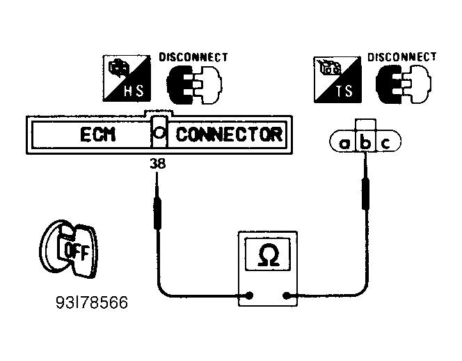
- Check Input Signal Circuit
- Disconnect ECM harness connector. See Figure
. Verify harness continuity between ECM connector terminal No. 38 and TPS connector terminal "b" (Black wire). See Figure
and Fig 4
. If continuity is present, go to next step. If continuity is not present, repair harness or connectors as necessary.
- Check Component
- Inspect TPS. See I - SYS/COMP TESTS article in the ENGINE PERFORMANCE Section. Replace TPS if necessary and perform FINAL CHECK
.
 Courtesy of NISSAN MOTOR CO., U.S.A.