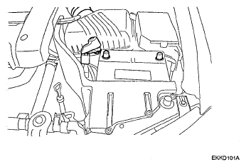
- Remove the battery terminal ("-", "+").
 Courtesy of HYUNDAI MOTOR CO.
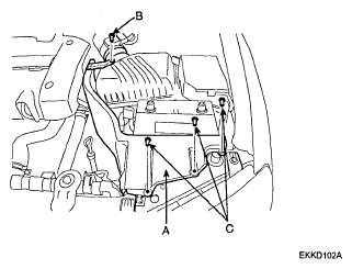
- Remove the heat shield (A). (Bolt: 1EA (B), Retainer: 3EA (C))
 Courtesy of HYUNDAI MOTOR CO.
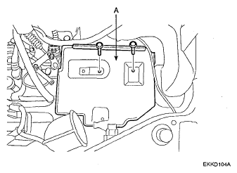
- Remove the battery and the battery tray (A).
 Courtesy of HYUNDAI MOTOR CO.
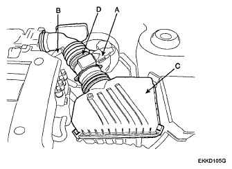
- Removal of air cleaner and air intake hose.
- Disconnect the air flow sensor connector (A) and breather hose (B).
- Air cleaner upper cover (C) and air intake hose (D).
 Courtesy of HYUNDAI MOTOR CO.
- Air cleaner lower (A) (Bolt: 3EA (B)). A
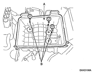 Courtesy of HYUNDAI MOTOR CO.
- Remove the solenoid valve connector (A).
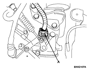 Courtesy of HYUNDAI MOTOR CO.
- Remove the transaxle range switch connector (A).
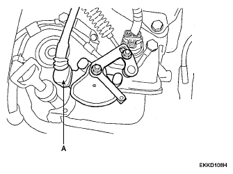 Courtesy of HYUNDAI MOTOR CO.
- Remove the control cable (A) to transaxle range switch mounting nut (B).
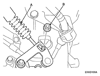 Courtesy of HYUNDAI MOTOR CO.
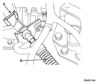
- Remove the clip (A) of the control cable (B).
 Courtesy of HYUNDAI MOTOR CO.
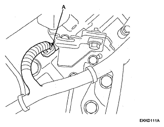
- Remove the input shaft speed sensor connector (A).
 Courtesy of HYUNDAI MOTOR CO.
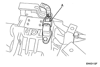
- Remove the output shaft speed sensor connector (A).
 Courtesy of HYUNDAI MOTOR CO.
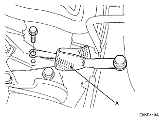
- Remove the transaxle earth cable (A).
 Courtesy of HYUNDAI MOTOR CO.
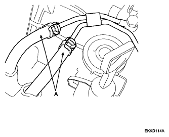
- Remove the oil cooler hose (A).
 Courtesy of HYUNDAI MOTOR CO.
NOTE:
To prevent entry of dust or foreign matter, plug the disconnected hoses and transaxle fittings.
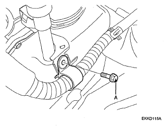
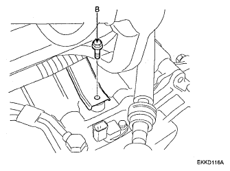
- Remove the start motor cable mounting bolts (A, B).
 Courtesy of HYUNDAI MOTOR CO.
 Courtesy of HYUNDAI MOTOR CO.
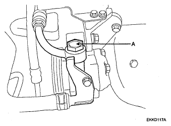
- Remove the power steering eye bolt (A).
 Courtesy of HYUNDAI MOTOR CO.
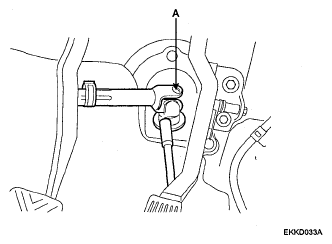
- Remove the steering u-joint (A) mounting bolt.
 Courtesy of HYUNDAI MOTOR CO.
NOTE:
Mark a mating line on the steering column universal joint and the gear box before disassembling to make the installation easier.
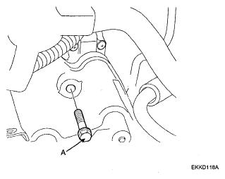
- Remove the start motor mounting bolt (A). (1EA)
 Courtesy of HYUNDAI MOTOR CO.
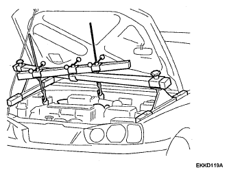
- Install the special tools (09200-38001,09200-1C000), the engine support fixture and the adapter, on the engine assembly.
 Courtesy of HYUNDAI MOTOR CO.
NOTE:
When using the special tool, be careful that the hook holder of the special tool doesn't wear the cowl top cover.
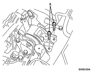
- Remove the transaxle-mounting bracket.
- Body mounting bolts (A) (Upper side)
 Courtesy of HYUNDAI MOTOR CO.
- Insulator bolt (A).
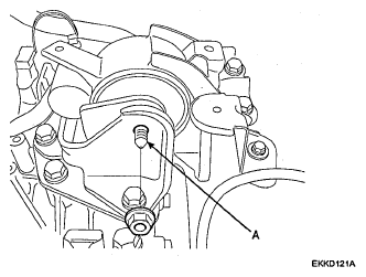 Courtesy of HYUNDAI MOTOR CO.
- Body mounting bolts (A) (Left side).
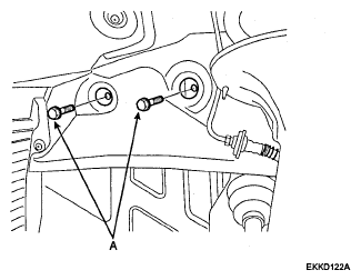 Courtesy of HYUNDAI MOTOR CO.
- Transaxle mounting bracket (A).
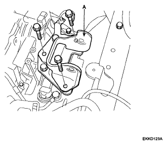 Courtesy of HYUNDAI MOTOR CO.
- Remove front oxygen sensor, engine oil pressure switch (A), crank position sensor (B) connector mounting bracket (C).
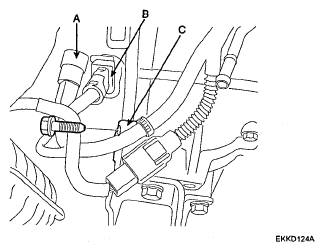 Courtesy of HYUNDAI MOTOR CO.
- Remove the transaxle mounting to the engine bolts (A).
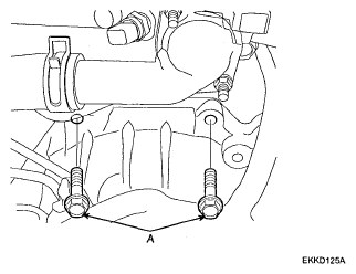 Courtesy of HYUNDAI MOTOR CO.
- Lift up the vehicle.
- Remove the drain plug (A) and drain the automatic transaxle fluid.
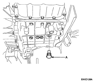 Courtesy of HYUNDAI MOTOR CO.
- Remove the tire
- Separate the tie rod end (A) from the pin (B) and nut (C).
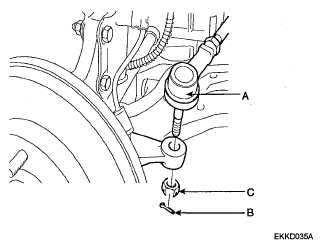 Courtesy of HYUNDAI MOTOR CO.
- Remove the pin (A) and hub nut (B) from the front axle (C).
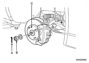 Courtesy of HYUNDAI MOTOR CO.
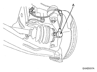
- Remove the ABS wheel speed sensor (A).
 Courtesy of HYUNDAI MOTOR CO.
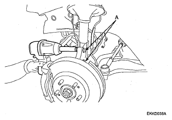
- Remove the knuckle mounting bolts (A).
 Courtesy of HYUNDAI MOTOR CO.
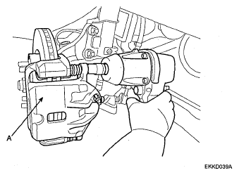
- Remove the caliper (A).
 Courtesy of HYUNDAI MOTOR CO.
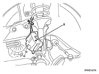
- Hang the caliper assembly (A).
 Courtesy of HYUNDAI MOTOR CO.
- Remove the knuckle from the drive shaft.
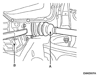
- Remove the drive shaft (A) from the transaxle (B).
 Courtesy of HYUNDAI MOTOR CO.
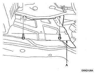
- Remove the side cover (A).
 Courtesy of HYUNDAI MOTOR CO.
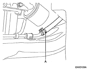
- Remove the power return hose (A) and drain the power steering oil.
 Courtesy of HYUNDAI MOTOR CO.
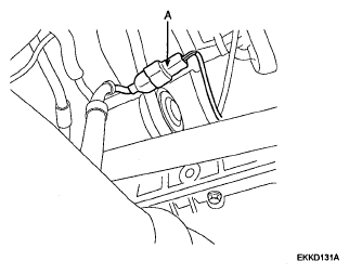
- Disconnect the rear oxygen sensor connector (A).
 Courtesy of HYUNDAI MOTOR CO.
- Remove the front muffler (A).
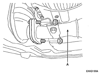 Courtesy of HYUNDAI MOTOR CO.
- Remove the front roll stopper-mounting bolt (A).
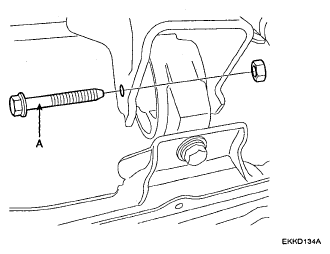 Courtesy of HYUNDAI MOTOR CO.
- Remove the rear roll stopper-mounting bolt (A).
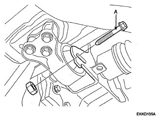 Courtesy of HYUNDAI MOTOR CO.
- Remove the vehicle speed sensor connector (A).
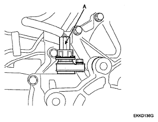 Courtesy of HYUNDAI MOTOR CO.
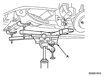
- Install the jack (A).
 Courtesy of HYUNDAI MOTOR CO.
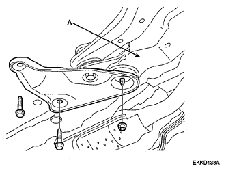
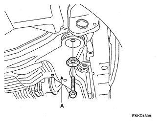
- Remove the sub frame (A).
 Courtesy of HYUNDAI MOTOR CO.
 Courtesy of HYUNDAI MOTOR CO.
- Remove the start motor mounting bolt.
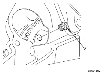
- Remove the engine to the torque converter mounting bolts (A). (4EA)
 Courtesy of HYUNDAI MOTOR CO.
- Install the jack (A) for supporting transaxle.
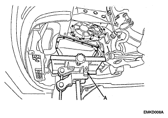 Courtesy of HYUNDAI MOTOR CO.
- Remove the engine to automatic transaxle mounting bolts.
- Transaxle to engine mounting bolt (A).
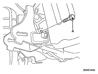 Courtesy of HYUNDAI MOTOR CO.
- Engine to transaxle mounting bolt (A).
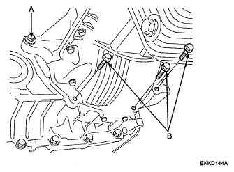 Courtesy of HYUNDAI MOTOR CO.
- Engine oil pan to transaxle mounting bolts (B).
- Remove the transaxle.