Test Procedure
- Turn ignition off. Connect Hi-Scan Pro tool or equivalent to OBD-II Data Link Connector (DLC). See Figure. Turn ignition on. Monitor for DTCs. Verify DTC P0340 is set and go to next step.
- Turn ignition on. Backprobe and measure voltage between ground and CMP sensor connector terminal No. 1 (Gray wire). Voltage should be battery voltage. If voltage is as specified, go to next step. If voltage is not as specified, repair open or short circuit (in Gray wire) between CMP sensor and ECM control relay. For circuits identification, see WIRING DIAGRAMS
article. After repair go to step 9.
- Start engine and let it idle. While racing engine speed between 700-3000 RPM, backprobe and measure voltage between ground and CMP sensor connector terminal No. 2 (White/Black wire) and No. 3 (Black wire). Both voltages should be between 0-5 volts. If voltages are as specified, go to next step. If any voltage is not as specified, replace CMP sensor with known-good component. After repair, go to step 9.
- Turn ignition off. Disconnect CMP 3-pin harness connector. See Fig 1 and ECM 81-pin harness connector. See Figure. Measure resistance between CMP sensor connector terminal No. 2 and ECM connector terminal No. 79 (White/Black wire). Resistance should be one ohm or less. If resistance is as specified, go to next step. If resistance is not as specified, repair open or short circuit (in White/Black wire) between CMP sensor and ECM. After repair, go to step 9.
- With CMP sensor and ECM harness connectors disconnected. Measure resistance between ground and CMP sensor connector terminal No. 2 (White/Black wire). Resistances should be infinity. If resistance is as specified, go to next step. If resistance is not as specified, repair short circuit (in White/Black wire) between CMP sensor and ECM. After repair, go to step 9.
- With CMP sensor and ECM harness connectors disconnected. Measure resistance between ground and CMP sensor connector terminal No. 3 (Black wire). Resistances should be one ohm or less. If resistanceis as specified, go to next step. If resistance is not as specified, repair short circuit (in Black wire) between CMP sensor and ground. After repair, go to step 9.
- Inspect CMP sensor for debris or misadjustment. Also perform ignition timing inspection. See appropriate ON VEHICLE ADJUSTMENT article. If CMP sensor and ignition timing are as specified, go to next step. If CMP sensor and ignition timing are not as specified, repair or replace as necessary and go to step 9.
- Verify than CMP sensor and ECM connectors are secure. If connectors are okay, replace ECM with known-good component and go to next step.
- Return vehicle to original condition. Clear codes using Hi-Scan Pro tool or equivalent. Verify repairs by driving vehicle and monitoring for pending codes. If DTC is set during test drive, follow appropriate DTC test procedure.
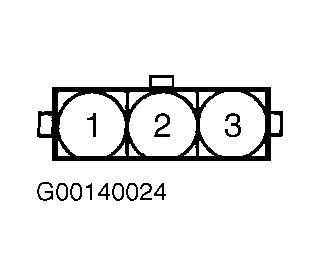 Courtesy of HYUNDAI MOTOR CO.