Gauge Control Module Connector for Inputs and Outputs
| Connector Index |
| GAUGE CONTROL MODULE CONNECTOR A (32P) |
| GAUGE CONTROL MODULE CONNECTOR B (12P) |
| GAUGE CONTROL MODULE CONNECTOR C (3P) |
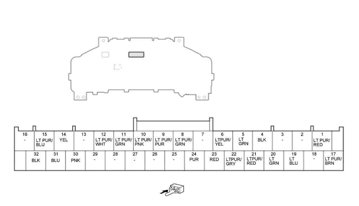
Gauge Control Module Connector A (32P) (female terminals)
 Courtesy of HONDA, U.S.A., INC. Courtesy of HONDA, U.S.A., INC.
|
| Terminal number |
Terminal name |
Description |
Signal |
| 1 |
+B BACK UP |
Power source for gauge control module |
About battery voltage at all times |
| 2 |
Not used |
--- |
--- |
| 3 |
Not used |
--- |
--- |
| 4 |
GND |
Ground for gauge control module |
Less than 0.2 V at all times |
| 5 |
CRUISE GND |
Ground for ACC combination switch |
Less than 0.2 V at all times |
| 6 |
SPORT MODE SW |
Detects SPORT MODE SW signal |
With vehicle in ON mode and sport mode switch released: about battery voltage With vehicle in ON mode and sport mode switch pressed: less than 0.2 V |
| 7 |
Not used |
--- |
--- |
| 8 |
ECON SW |
Detects ECON SW signal |
With vehicle in ON mode and ECON switch released: about battery voltage With vehicle in ON mode and ECON switch pressed: less than 0.2 V |
| 9 |
VSA OFF SW |
Detects VSA OFF SW signal |
With vehicle in ON mode and VSA off switch released: about battery voltage With vehicle in ON mode and VSA off switch pressed: less than 0.2 V |
| 10 |
PARK LAMP |
Detects PARK LAMP signal |
With electric parking brake non-operation: about battery voltage With electric parking brake operation: less than 0.2 V |
| 11 |
BRAKE LEVEL SW |
Detects BRAKE LEVEL SW signal |
With vehicle in ON mode and brake fluid level switch OFF: about battery voltage With vehicle in ON mode and brake fluid level switch ON: less than 0.2 V |
| 12 |
BRAKE HOLD SW |
Detects BRAKE HOLD SW signal |
With vehicle in ON mode and electric parking brake non-operation: about battery voltage With vehicle in ON mode and electric parking brake operation: less than 0.2 V |
| 13 |
Not used |
--- |
--- |
| 14 |
CRUISE SW |
Detects CRUISE SW signal |
With vehicle in ON mode: about 0.8-4.4 V (depending on ACC combination switch) |
| 15 |
ILL-(LED) |
Outputs ILL-(LED) signal |
--- |
| Terminal number |
Terminal name |
Description |
Signal |
| 16 |
Not used |
--- |
--- |
| 17 |
IG1 METER |
IG1 power source |
With vehicle in ON or READY TO DRIVE mode: about battery voltage |
| 18 |
Not used |
--- |
--- |
| 19 |
F-CAN B_H |
Communication line |
--- |
| 20 |
F-CAN B_L |
Communication line |
--- |
| 21 |
FUEL GAUGE- |
Ground for fuel gauge sending unit |
--- |
| 22 |
FUEL GAUGE+ |
Detects FUEL GAUGE+ signal |
--- |
| 23 |
LIN(START SW) |
Communication line |
--- |
| 24 |
WASHER LEVEL SNSR |
Detects WASHER LEVEL SNSR signal |
With vehicle in ON mode and washer fluid level switch OFF: about battery voltage With vehicle in ON mode and washer fluid level switch ON: less than 0.2 V |
| 25 |
Not used |
--- |
--- |
| 26 |
Not used |
--- |
--- |
| 27 |
Not used |
--- |
--- |
| 28 |
Not used |
--- |
--- |
| 29 |
Not used |
--- |
--- |
| 30 |
B-CAN_H |
Communication line |
--- |
| 31 |
B-CAN_L |
Communication line |
--- |
| 32 |
GND |
Ground for gauge control module |
Less than 0.2 V at all times |
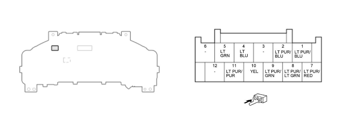
Gauge Control Module Connector B (12P) (female terminals)
 Courtesy of HONDA, U.S.A., INC. Courtesy of HONDA, U.S.A., INC.
|
| Terminal number |
Terminal name |
Description |
Signal |
| 1 |
WUMC |
Detects WUMC signal |
--- |
| 2 |
WUCM |
Detects WUCM signal |
--- |
| 3 |
Not used |
--- |
--- |
| 4 |
HV SW |
Detects HV SW signal |
With vehicle in ON mode and HV switch released: about battery voltage With vehicle in ON mode and HV switch pressed: less than 0.2 V |
| 5 |
DMOMTRWK |
Detects DMOMTRWK signal |
--- |
| 6 |
Not used |
--- |
--- |
| 7 |
ILLUMI-SIG |
Detects ILLUMI-SIG signal |
With vehicle in ON mode and dashlights brightness control switch (-) released: about battery voltage With vehicle in ON mode and dashlights brightness control switch (-) pressed: less than 0.2 V |
| 8 |
ILLUMI+SIG |
Detects ILLUMI+SIG signal |
With vehicle in ON mode and dashlights brightness control switch (+) released: about battery voltage With vehicle in ON mode and dashlights brightness control switch (+) pressed: less than 0.2 V |
| Terminal number |
Terminal name |
Description |
Signal |
| 9 |
CMBS OFF SW |
Detects CMBS OFF SW signal |
With vehicle in ON mode and CMBS OFF switch released: about battery voltage With vehicle in ON mode and CMBS OFF switch pressed: less than 0.2 V |
| 10 |
DISTANCE SW |
Detects DISTANCE SW signal |
With vehicle in ON mode: about 0.8-4.4 V (depending on ACC combination switch) |
| 11 |
ODO/TRIP |
Detects ODO/TRIP signal |
With vehicle in ON mode and TRIP switch released: about battery voltage With vehicle in ON mode and TRIP switch pressed: less than 0.2 V |
| 12 |
Not used |
--- |
--- |
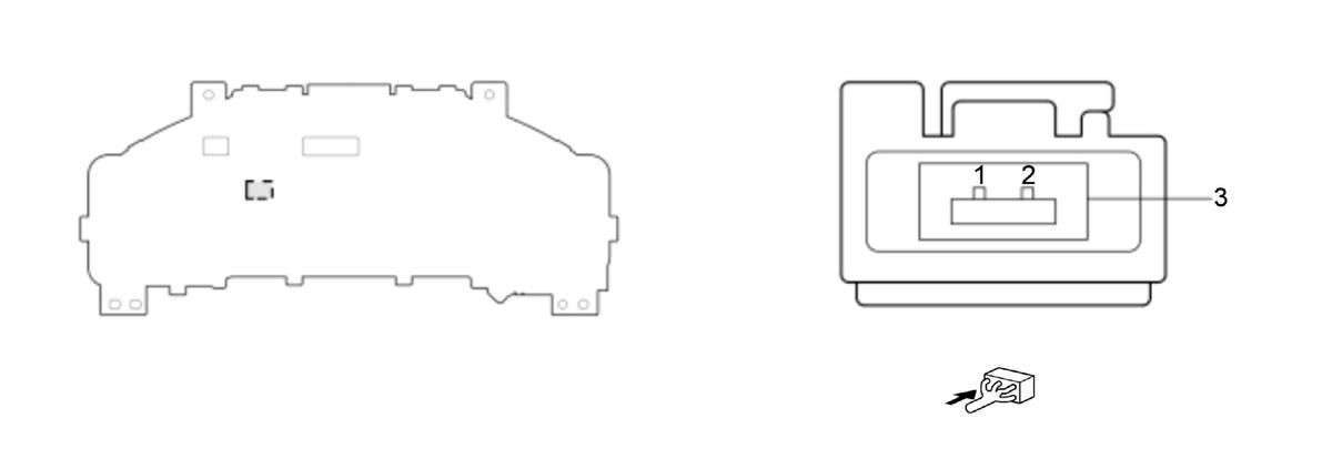
Gauge Control Module Connector C (3P) (female terminals)
 Courtesy of HONDA, U.S.A., INC. Courtesy of HONDA, U.S.A., INC.
|
| Terminal number |
Terminal name |
Description |
Signal |
| 1 |
LVDS2+ |
LVDS2+ signal |
--- |
| 2 |
LVDS2- |
LVDS2- signal |
--- |
| 3 |
SH LVDS |
SH LVDS signal |
--- |