Shift Lever Knob Replacement
- Remove the shift lever assembly (see
SHIFT LEVER REMOVAL ).
- Remove the harness clamp and the harness wire ties from the shift lever bracket, and remove the harnesses from the harness clamp and the harness wire ties.
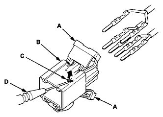
- Pry up the lock covers (A) of the D3 switch/shift lock solenoid/park pin switch connector (B).
 Courtesy of AMERICAN HONDA MOTOR CO., INC.
- Remove the terminal from the connector by pushing the lock tab (C) up in the connector using a thin blade screwdriver (D). Remove all six terminals, and replace the connector.
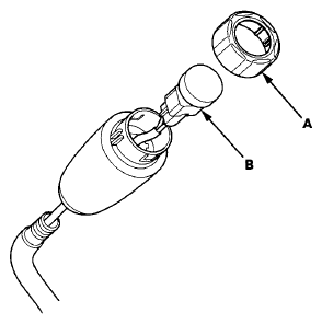
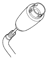
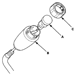
- Pry off the shift lever knob ring (A), and remove it.
 Courtesy of AMERICAN HONDA MOTOR CO., INC.
- Unlatch the D3 switch harness clamp on the shift lever bracket, pry out the D3 switch (B), and pull it from the knob.
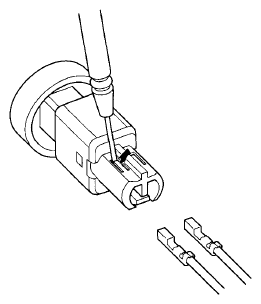
- Remove the D3 switch harness terminals by prying the lock tabs up with a thin blade screwdriver.
 Courtesy of AMERICAN HONDA MOTOR CO., INC.
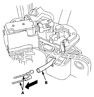
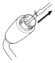
- Pull the D3 switch harness wires (A) from shift lever bracket side, and remove the harness wires. Leave the harness tube (B) and remove only the wires.
 Courtesy of AMERICAN HONDA MOTOR CO., INC.
- Remove the shift lever knob from the shift lever.
 Courtesy of AMERICAN HONDA MOTOR CO., INC.
- Install a new shift lever knob on the shift lever.
- Insert new D3 switch harness wires (A) in the original harness tube (B), then tie a string (C) around the tube to secure the terminals in the tube.
 Courtesy of AMERICAN HONDA MOTOR CO., INC.
- Pull the old tube out of the shift lever knob side to install the D3 switch harness wires.
 Courtesy of AMERICAN HONDA MOTOR CO., INC.
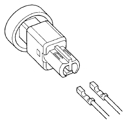
- Remove the old harness tube from the D3 switch harness terminals.
- Install the D3 switch harness terminals in the new D3 switch. Either harness terminal can be installed in either cavity.
 Courtesy of AMERICAN HONDA MOTOR CO., INC.
- Install the D3 switch (A) in the shift lever knob (B).
 Courtesy of AMERICAN HONDA MOTOR CO., INC.
- Install the new shift lever knob ring (C).
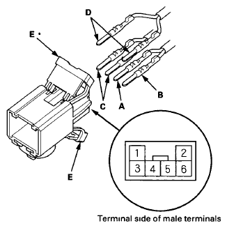
- Install the RED harness terminal (A) of the shift lock solenoid in the No. 5 cavity, and the BLK harness terminal (B) in the No. 6 cavity.
 Courtesy of AMERICAN HONDA MOTOR CO., INC.
- Install the D3 switch harness terminals (WHT) (C) in the No. 3 and No. 4 cavities. Either D3 switch harness terminal can be installed in the No. 3 and No. 4 cavities.
- Install the park pin switch harness terminals (BLK) (D) in the No. 1 and No. 2 cavities. Either park pin switch harness terminal can be installed in the No. 1 and No. 2 cavities.
- Make sure that all six terminals lock securely, then install the lock covers (E) securely in place.
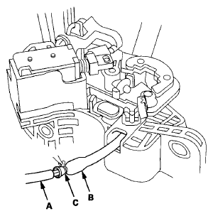
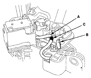
- Install the D3 switch harness (A) in the harness clamp (B) at the mark (C).
 Courtesy of AMERICAN HONDA MOTOR CO., INC.
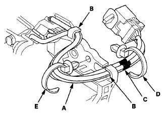
- Route the harnesses (A) through the guides (B).
 Courtesy of AMERICAN HONDA MOTOR CO., INC.
- Align the marks (C) on each harness, and tie the harness together into bundle with a new harness wire tie (D) over the marks.
- Tie the harness together into bundle with a new harness wire tie, then install the harness wire tie (E) on the shift lever bracket.
- Install the shift lever assembly (see
SHIFT LEVER INSTALLATION ).
- Check that the D3 switch operates.