Audio Unit Connector for Inputs and Outputs
When replacing an audio unit connector, match the wires to the cavities listed in the following table.
'07 model with premium audio system/with navigation
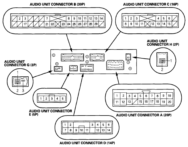 Courtesy of AMERICAN HONDA MOTOR CO., INC.
'08-10 models with premium audio system/with navigation
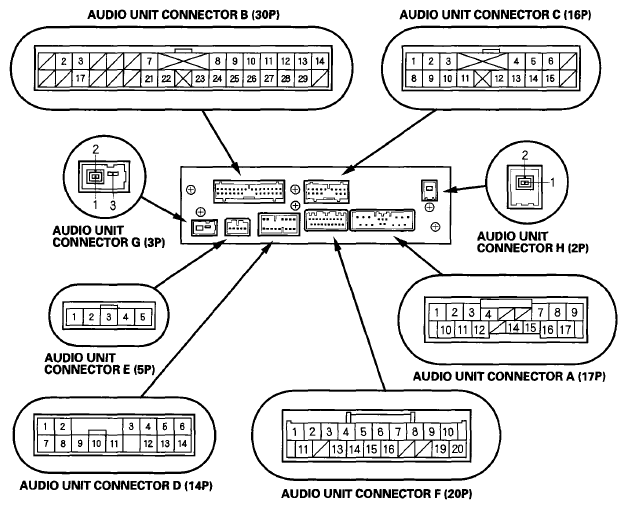 Courtesy of AMERICAN HONDA MOTOR CO., INC.
AUDIO UNIT CONNECTOR A (20P) ('07 model)
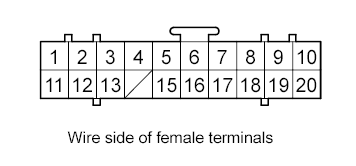 Courtesy of AMERICAN HONDA MOTOR CO., INC.
 AUDIO UNIT CONNECTOR REFERENCE
| Cavity |
Wire |
Connect to |
| A1 |
YEL/GRN |
Stereo amplifier (RADIO SWD +B) |
| A2 |
YEL/RED |
No. 32 (10 A) fuse in the driver's under-dash fuse/relay box (ACC) |
| A3 |
WHT |
Audio remote switch (AUDIO REMOTE) |
| A4 |
GRN/ORN |
Audio disc changer (SCTY6) |
| A5 |
BRN |
Stereo amplifier (RR PRE IN+) |
| A6 |
LT BLU |
Stereo amplifier (RL PRE IN+) |
| A7 |
GRN |
Stereo amplifier (FR PRE IN+) |
| A8 |
BLU |
Stereo amplifier (FL PRE IN+) |
| A9 |
RED/BLK |
No. 7 (7.5 A) fuse in the passenger's under-dash fuse/relay box (ILL+) |
| A10 |
WHT/GRN |
No. 5 (10 A) fuse in the driver's under-dash fuse/relay box (+B) |
| A11 |
BRN |
Remote switch ground (REMOTE GND) |
| A12 |
YEL |
Navigation unit (RG GND) |
| A13 |
RED/BLU |
Navigation unit (RG L+) |
| A15 |
YEL |
Stereo amplifier (RR PRE IN-) |
| A16 |
PUR |
Stereo amplifier (RL PRE IN-) |
| A17 |
RED |
Stereo amplifier (FR PRE IN-) |
| A18 |
PNK |
Stereo amplifier (FL PRE IN-) |
| A19 |
RED |
Dash lights brightness controller (ILL-) |
| A20 |
BLK |
Body ground to G503 (GND) |
AUDIO UNIT CONNECTOR A (17P) ('08-10 models)
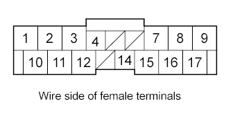 Courtesy of AMERICAN HONDA MOTOR CO., INC.
 AUDIO UNIT CONNECTOR REFERENCE
| Cavity |
Wire |
Connect to |
| A1 |
RED |
Dash lights brightness controller (ILL-) |
| A2 |
PUR |
Stereo amplifier (RL PRE IN-) |
| A3 |
PNK |
Stereo amplifier (FL PRE IN-) |
| A4 |
GRN/ORN |
Audio disc changer (SCTY6) |
| A7 |
RED |
Stereo amplifier (FR PRE IN-) |
| A8 |
YEL |
Stereo amplifier (RR PRE IN-) |
| A9 |
BLK |
Body ground to G503 (GND) |
| A10 |
RED/BLK |
No. 7 (7.5 A) fuse in the passenger's under-dash fuse/relay box (ILL+) |
| A11 |
LT BLU |
Stereo amplifier (RL PRE IN+) |
| A12 |
BLU |
Stereo amplifier (FL PRE IN+) |
| A14 |
YEL/RED |
No. 32 (10 A) fuse in the driver's under-dash fuse/relay box (ACC) |
| A15 |
GRN |
Stereo amplifier (FR PRE IN+) |
| A16 |
BRN |
Stereo amplifier (RR PRE IN+) |
| A17 |
WHT/GRN |
No. 5 (10 A) fuse in the driver's under-dash fuse/relay box (+B) |
AUDIO UNIT CONNECTOR B (30P)
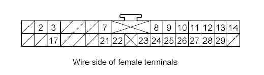 Courtesy of AMERICAN HONDA MOTOR CO., INC.
 AUDIO UNIT CONNECTOR REFERENCE
| Cavity |
Wire |
Connect to |
| B2 |
BLU |
Rear controller and screen (RR NTSC) |
| B3 |
GRY |
Shield for terminals No. 2 and No. 7 (RR NTSC SH) |
| B7 |
GRY |
Shield for terminals No. 21 and No. 22 (VIDEO1 SH) |
| B8 |
BRN |
Auxiliary jack assembly (HP L OUT) |
| B9 |
GRV |
Shield for terminals No. 8, No. 24, and No. 25 (HP R/L OUT SH) |
| B10 |
GRY |
Shield for terminals No. 11, No. 12, and No. 13 (HP R/L SH) |
| B11 |
WHT |
Rear controller and screen (HPR/LGND) |
| B12 |
RED |
Rear controller and screen (HPL) |
| B13 |
BLK |
Rear controller and screen (HPR) |
| B14 |
YEL/RED |
Rear controller and screen (SYSTEM ACC) |
| B17 |
PNK |
Rear controller and screen (RR NTSC GND) |
| B21 |
LT BLU |
Auxiliary jack assembly (VIDEO1 GND) |
| B22 |
PUR |
Auxiliary jack assembly (VIDEO1) |
| B23 |
WHT/GRN |
Auxiliary jack assembly (COMN CHK) |
| B24 |
ORN |
Auxiliary jack assembly (HP ROUT) |
| B25 |
YEL |
Auxiliary jack assembly (HP R/L OUT GND) |
| B26 |
GRY |
Shield for terminals No. 27, No. 28, and No. 29 (VIDE01 R/L SH) |
| B27 |
PNK |
Auxiliary jack assembly (VIDEO1 R/L GND) |
| B28 |
GRN |
Auxiliary jack assembly (VIDEO1 L) |
| B29 |
BLU |
Auxiliary jack assembly (VIDEO1 R) |
AUDIO UNIT CONNECTOR C (16P)
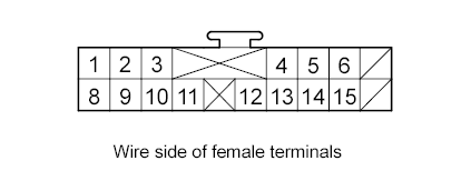 Courtesy of AMERICAN HONDA MOTOR CO., INC.
 AUDIO UNIT CONNECTOR REFERENCE
| Cavity |
Wire |
Connect to |
| C1 |
WHT |
DVD player unit (DVD R/L GND) |
| C2 |
BLK |
DVD player unit (DVD L) |
| C3 |
RED |
DVD player unit (DVD R) |
| C4 |
GRY |
Shield for terminals No. 5 and No. 6 (DVD SH) |
| C5 |
PNK |
DVD player unit (DVD GND) |
| C6 |
BLU |
DVD player unit (DVD) |
| C8 |
GRY |
Shield for terminals No. 1, No. 2, and No. 3 (DVD R/L SH) |
| C9 |
LT BLU |
Rear controller and screen (GA-NET RR BUS+) |
| C10 |
GRY |
Shield for terminals No. 9 and No. 11 (GA-NET RR BUS SH) |
| C11 |
PUR |
Rear controller and screen (GA-NET RR BUS-) |
| C12 |
ORN |
DVD player unit (Rx) |
| C13 |
BRN |
DVD player unit (Tx) |
| C14 |
YEL |
DVD player unit (Tx/Rx GND) |
| C15 |
GRY |
Shield for terminals No. 12, No. 13, and No. 14 (Tx/Rx SH) |
AUDIO UNIT CONNECTOR D (14P)
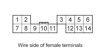 Courtesy of AMERICAN HONDA MOTOR CO., INC.
 AUDIO UNIT CONNECTOR REFERENCE
| Cavity |
Wire |
Connect to |
| D1 |
RED/BLU |
Audio disc changer (GA-NET +B) |
| D2 |
BLU/RED |
Audio disc changer (SYSTEM ACC) |
| D3 |
GRY |
Shield for terminals No. 9 and No. 10 (GA-NET AUDIO BUS2 SH) |
| D4 |
GRV |
Shield for terminals No. 5, No. 6, No. 13, and No. 14 (AUDIO 2 SH) |
| D5 |
RED |
Audio disc changer (AUDIO 2 R+) |
| D6 |
BLK |
Audio disc changer (AUDIO 2 L+) |
| D7 |
RED/YEL |
Audio disc changer (GA-NET +B) |
| D8 |
GRN/RED |
Audio disc changer (GA-NET ILL+) |
| D9 |
LT BLU |
Audio disc changer (GA-NET AUDIO BUS2+) |
| D10 |
PUR |
Audio disc changer (GA-NET AUDIO BUS2-) |
| D11 |
WHT/BLK |
Audio disc changer (GA-NET GND) |
| D12 |
GRN/WHT |
Audio disc changer (GA-NET ILL CTRL) |
| D13 |
WHT |
Audio disc changer (AUDIO 2 R-) |
| D14 |
GRN |
Audio disc changer (AUDIO 2 L-) |
AUDIO UNIT CONNECTOR E (5P)
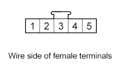 Courtesy of AMERICAN HONDA MOTOR CO., INC.
 AUDIO UNIT CONNECTOR REFERENCE
| Cavity |
Wire |
Connect to |
| E1 |
BLK |
Active noise cancellation unit (ANC FR+) |
| E2 |
GRN |
Active noise cancellation unit (ANC FR-) |
| E3 |
RED |
Active noise cancellation unit (ANC RR+) |
| E4 |
WHT |
Active noise cancellation unit (ANC RR-) |
| E5 |
BRN |
Active noise cancellation unit (ANC CHK2) |
AUDIO UNIT CONNECTOR F (20P) ('08-10 models)
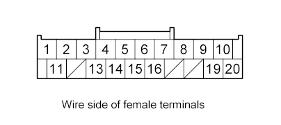 Courtesy of AMERICAN HONDA MOTOR CO., INC.
 AUDIO UNIT CONNECTOR REFERENCE
| Cavity |
Wire |
Connect to |
| F1 |
YEL |
Navigation unit (RG GND) |
| F2 |
GRY |
Shield for terminals No. 1 and No. 11 (RG SH GND) |
| F3 |
BLK |
Auxiliary jack assembly (AUX S GND) |
| F4 |
GRY |
Shield for terminals No. 3, No. 13, and No. 14 (AUX SH GND) |
| F5 |
LT GRN |
Auxiliary jack assembly (AUX GND) |
| F6 |
BRN |
Remote switches ground (REMOTE GND) |
| F7 |
WHT |
Audio remote switch (AUDIO REMOTE) |
| F8 |
PNK |
HandsFreeLink control unit (HFL ICON) |
| F9 |
RED |
HandsFreeLink control unit (TELM SIG-) |
| F10 |
GRY |
Shield for terminals No. 9 and No. 19 (TELM SH GND) |
| F11 |
RED/BLU |
Navigation unit (RG L+) |
| F13 |
WHT |
Auxiliary jack assembly (AUX L) |
| F14 |
RED |
Auxiliary jack assembly (AUX R) |
| F15 |
LT BLU |
Auxiliary jack assembly (AUX DET) |
| F16 |
YEL/GRN |
Stereo amplifier (SWD +B) |
| F19 |
GRN |
HandsFreeLink control unit (TELM SIG+) |
| F20 |
LT GRN |
HandsFreeLink control unit (HFL MUTE) |
AUDIO UNIT CONNECTOR G (3P)
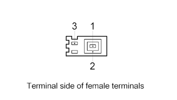 Courtesy of AMERICAN HONDA MOTOR CO., INC.
 AUDIO UNIT CONNECTOR REFERENCE
| Cavity |
Wire |
Connect to |
| G1 |
- |
AM/FM antenna amplifier (SIG) |
| G2 |
- |
Shield for terminal No. 1 (SH (AM/FM)) |
| G3 |
- |
AM/FM antenna amplifier (ANT+B) |
AUDIO UNIT CONNECTOR H (2P)
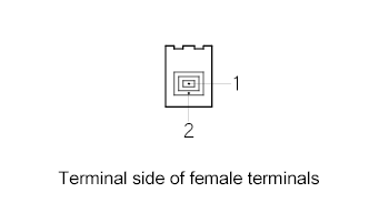 Courtesy of AMERICAN HONDA MOTOR CO., INC.
 AUDIO UNIT CONNECTOR REFERENCE
| Cavity |
Wire |
Connect to |
| H1 |
- |
DVD player unit (DIGITAL SIG) |
| H2 |
- |
Shield for terminal No. 1 (DIGITAL SH) |
When replacing an audio unit connector, match the wires to the cavities listed in the following table.
'07 model without premium audio system/with navigation
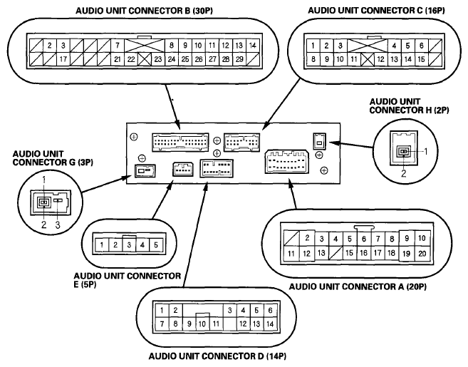 Courtesy of AMERICAN HONDA MOTOR CO., INC.
'08-10 models without premium audio system/with navigation
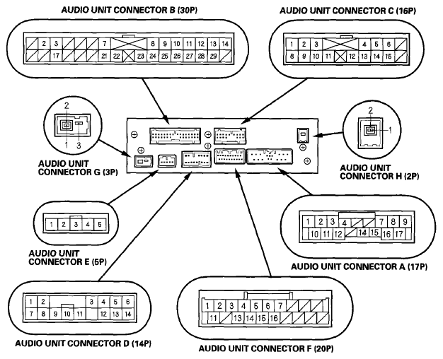 Courtesy of AMERICAN HONDA MOTOR CO., INC.
AUDIO UNIT CONNECTOR A (20P) ('07 model)
Courtesy of AMERICAN HONDA MOTOR CO., INC. AUDIO UNIT CONNECTOR REFERENCE
| Cavity |
Wire |
Connect to |
| A2 |
YEL/RED |
No. 32 (10 A) fuse in the driver's under-dash fuse/relay box (ACC) |
| A3 |
WHT |
Audio remote switch (AUDIO REMOTE) |
| A4 |
GRN/ORN |
Audio disc changer (SCTY6) |
| A5 |
PNK |
Right rear speaker+ (RR R SPKR+) |
| A6 |
BLU/WHT |
Left rear speaker+ (RR L SPKR+) |
| A7 |
GRN/YEL |
Front passenger's door speaker+, Right tweeter+ (FR R SPKR+) |
| A8 |
GRN/BLU |
Driver's door speaker+, Left tweeter+ (FR L SPKR+) |
| A9 |
RED/BLK |
No. 7 (7.5 A) fuse in the passenger's under-dash fuse/relay box (ILL+) |
| A10 |
WHT/GRN |
No. 5 (10 A) fuse in the driver's under-dash fuse/relay box (+B) |
| A11 |
BRN |
Remote switches ground (REMOTE GND) |
| A12 |
YEL |
Navigation unit (RG GND) |
| A13 |
RED/BLU |
Navigation unit (RG L+) |
| A15 |
BLU/YEL |
Right rear speaker- (RR R SPKR-) |
| A16 |
BLU/BLK |
Left rear speaker- (RR L SPKR-) |
| A17 |
GRY/RED |
Front passenger's door speaker-, Right tweeter- (FR R SPKR-) |
| A18 |
LT GRN |
Driver's door speaker-, Left tweeter-(FR L SPKR-) |
| A19 |
RED |
Dash lights brightness controller (ILL-) |
| A20 |
BLK |
Body ground to G503 (GND) |
AUDIO UNIT CONNECTOR A (17P) ('08-10 models)
Courtesy of AMERICAN HONDA MOTOR CO., INC. AUDIO UNIT CONNECTOR REFERENCE
| Cavity |
Wire |
Connect to |
| A1 |
RED |
Dash lights brightness controller (ILL-) |
| A2 |
BLU/RED |
Left rear speaker- (RR L SPKR-) |
| A3 |
LT GRN |
Driver's door speaker-, Left tweeter- (FR L SPKR-) |
| A4 |
GRN/ORN |
Audio disc changer (SCTY6) |
| A7 |
GRY/RED |
Front passenger's door speaker-. Right tweeter- (FR R SPKR-) |
| A8 |
BLU/YEL |
Right rear speaker- (RR R SPKR-) |
| A9 |
BLK |
Body ground to G503 (GND) |
| A10 |
RED/BLK |
No. 7 (7.5 A) fuse in the passenger's under-dash fuse/relay box (ILL+) |
| A11 |
BLU/WHT |
Left rear speaker+ (RR L SPKR) |
| A12 |
GRN/BLK |
Driver's door speaker+, Left tweeter+ (FR L SPKR+) |
| A14 |
YEL/RED |
No. 32 (10 A) fuse in the driver's under-dash fuse/relay box (ACC) |
| A15 |
GRN/YEL |
Front passenger's door speaker+. Right tweeter+ (FR R SPKR+) |
| A16 |
PNK |
Right rear speaker+ (RR R SPKR+) |
| A17 |
WHT/GRN |
No. 5 (10 A) fuse in the driver's under-dash fuse/relay box (+B) |
AUDIO UNIT CONNECTOR B (30P)
Courtesy of AMERICAN HONDA MOTOR CO., INC. AUDIO UNIT CONNECTOR REFERENCE
| Cavity |
Wire |
Connect to |
| B2 |
BLU |
Rear controller and screen (RR NTSC) |
| B3 |
GRY |
Shield for terminals No. 2 and No. 7 (RR NTSC SH) |
| B7 |
GRY |
Shield for terminals No. 21 and No. 22 (VIDE01 SH) |
| B8 |
BRN |
Auxiliary jack assembly (HP LOUT) |
| B9 |
GRY |
Shield for terminals No. 8, No. 24, and No. 25 (HP R/L OUT SH) |
| B10 |
GRY |
Shield for terminals No. 11, No. 12, and No. 13 (HP R/L SH) |
| B11 |
WHT |
Rear controller and screen (HP R/L GND) |
| B12 |
RED |
Rear controller and screen (HPL) |
| B13 |
BLK |
Rear controller and screen (HPR) |
| B14 |
YEL/RED |
Rear controller and screen (SYSTEM ACC) |
| B17 |
PNK |
Rear controller and screen (RR NTSC GND) |
| B21 |
LT BLU |
Auxiliary jack assembly (VIDE01 GND) |
| B22 |
PUR |
Auxiliary jack assembly (VIDE01) |
| B23 |
WHT/GRN |
Auxiliary jack assembly (COMN CHK) |
| B24 |
ORN |
Auxiliary jack assembly (HP R OUT) |
| B25 |
YEL |
Auxiliary jack assembly (HP R/L OUT GND) |
| B26 |
GRY |
Shield for terminals No. 27, No. 28, and No. 29 (VIDE01 R/L SH) |
| B27 |
PNK |
Auxiliary jack assembly (VIDE01 R/L GND) |
| B28 |
GRN |
Auxiliary jack assembly (VIDE01 L) |
| B29 |
BLU |
Auxiliary jack assembly (VIDE01 R) |
AUDIO UNIT CONNECTOR C (16P)
Courtesy of AMERICAN HONDA MOTOR CO., INC. AUDIO UNIT CONNECTOR REFERENCE
| Cavity |
Wire |
Connect to |
| C1 |
WHT |
DVD player unit (DVD R/L GND) |
| C2 |
BLK |
DVD player unit (DVD L) |
| C3 |
RED |
DVD player unit (DVD R) |
| C4 |
GRY |
Shield for terminals No. 5 and No. 6 (DVD SH) |
| C5 |
PNK |
DVD player unit (DVD GND) |
| C6 |
BLU |
DVD player unit (DVD) |
| C8 |
GRY |
Shield for terminals No. 1, No. 2, and No. 3 (DVD R/L SH) |
| C9 |
LT BLU |
Rear controller and screen (GA-NET RR BUS+) |
| C10 |
GRY |
Shield for terminals No. 9 and No. 11 (GA-NET RR BUS SH) |
| C11 |
PUR |
Rear controller and screen (GA-NET RR BUS-) |
| C12 |
ORN |
DVD player unit (Rx) |
| C13 |
BRN |
DVD player unit (Tx) |
| C14 |
YEL |
DVD player unit (Tx/Rx GND) |
| C15 |
GRY |
Shield for terminals No. 12, No. 13, and No. 14 (Tx/Rx SH) |
AUDIO UNIT CONNECTOR D (14P)
Courtesy of AMERICAN HONDA MOTOR CO., INC. AUDIO UNIT CONNECTOR REFERENCE
| Cavity |
Wire |
Connect to |
| D1 |
RED/BLU |
Audio disc changer (GA-NET +B) |
| D2 |
BLU/RED |
Audio disc changer (SYSTEM ACC) |
| D3 |
GRV |
Shield for terminals No. 9 and No. 10 (GA-NET AUDIO BUS2 SH) |
| D4 |
GRY |
Shield for terminals No. 5, No. 6, No. 13, and No. 14 (AUDIO 2 SH) |
| D5 |
RED |
Audio disc changer (AUDIO 2 R+) |
| D6 |
BLK |
Audio disc changer (AUDIO 2 L+) |
| D7 |
RED/YEL |
Audio disc changer (GA-NET +B) |
| D8 |
GRN/RED |
Audio disc changer (GA-NET ILL+) |
| D9 |
LT BLU |
Audio disc changer (GA-NET AUDIO BUS2+) |
| D10 |
PUR |
Audio disc changer (GA-NET AUDIO BUS2-) |
| D11 |
WHT/BLK |
Audio disc changer (GA-NET GND) |
| D12 |
GRN/WHT |
Audio disc changer (GA-NET ILL CTRL) |
| D13 |
WHT |
Audio disc changer (AUDIO 2 R-) |
| D14 |
GRN |
Audio disc changer (AUDIO 2 L-) |
AUDIO UNIT CONNECTOR E (5P)
Courtesy of AMERICAN HONDA MOTOR CO., INC. AUDIO UNIT CONNECTOR REFERENCE
| Cavity |
Wire |
Connect to |
| E1 |
BLK |
Active noise cancellation unit (ANC FR+) |
| E2 |
GRN |
Active noise cancellation unit (ANC FR-) |
| E3 |
RED |
Active noise cancellation unit (ANC RR+) |
| E4 |
WHT |
Active noise cancellation unit (ANC RR-) |
| E5 |
BRN |
Active noise cancellation unit (ANC CHK2) |
AUDIO UNIT CONNECTOR F (20P) ('08-10 models)
Courtesy of AMERICAN HONDA MOTOR CO., INC. AUDIO UNIT CONNECTOR REFERENCE
| Cavity |
Wire |
Connect to |
| F1 |
YEL |
Navigation unit (RG GND) |
| F2 |
GRN |
Shield for terminals No. 1 and No. 11 (RG SH GND) |
| F3 |
BLK |
Auxiliary jack assembly (AUX S GND) |
| F4 |
GRY |
Shield for terminals No. 3, No. 13, and No. 14 (AUX SH GND) |
| F5 |
LT GRN |
Auxiliary jack assembly (AUX GND) |
| F6 |
BRN |
Remote switches ground (REMOTE GND) |
| F7 |
WHT |
Audio remote switch (AUDIO REMOTE) |
| F11 |
RED/BLU |
Navigation unit (RG L+) |
| F13 |
WHT |
Auxiliary jack assembly (AUX L) |
| F14 |
RED |
Auxiliary jack assembly (AUX R) |
| F15 |
LT BLU |
Auxiliary jack assembly (AUX DET) |
| F16 |
YEL/GRN |
Active noise control unit (SWD +B) |
AUDIO UNIT CONNECTOR G (3P)
Courtesy of AMERICAN HONDA MOTOR CO., INC. AUDIO UNIT CONNECTOR REFERENCE
| Cavity |
Wire |
Connect to |
| G1 |
- |
AM/FM antenna amplifier (SIG) |
| G2 |
- |
Shield for terminal No. 1 (SH (AM/FM)) |
| G3 |
- |
AM/FM antenna amplifier (ANT +B) |
AUDIO UNIT CONNECTOR H (2P)
Courtesy of AMERICAN HONDA MOTOR CO., INC. AUDIO UNIT CONNECTOR REFERENCE
| Cavity |
Wire |
Connect to |
| H1 |
- |
DVD player unit (DIGITAL SIG) |
| H2 |
- |
Shield for terminal No. 1 (DIGITAL SH) |
When replacing an audio unit connector, match the wires to the cavities listed in the following table.
'07 model with premium audio system/without navigation
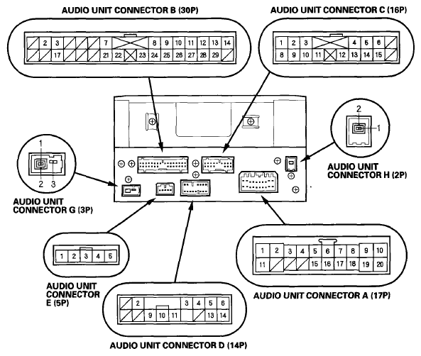 Courtesy of AMERICAN HONDA MOTOR CO., INC.
AUDIO UNIT CONNECTOR A (20P)
Courtesy of AMERICAN HONDA MOTOR CO., INC. AUDIO UNIT CONNECTOR REFERENCE
| Cavity |
Wire |
Connect to |
| A1 |
YEL/GRN |
Stereo amplifier (RADIO SWD +B) |
| A2 |
YEL/RED |
No. 32 (10 A) fuse in the driver's under-dash fuse/relay box (ACC) |
| A3 |
WHT |
Audio remote switch (AUDIO REMOTE) |
| A4 |
RED/WHT |
Rear controller and screen (SCTY3) |
| A5 |
BRN |
Stereo amplifier (RR PRE IN+) |
| A6 |
LT BLU |
Stereo amplifier (RL PRE IN+) |
| A7 |
GRN |
Stereo amplifier (FR PRE IN+) |
| A8 |
BLU |
Stereo amplifier (FL PRE IN+) |
| A9 |
RED/BLK |
No. 7 (7.5 A) fuse in the passenger's under-dash fuse/relay box (ILL+) |
| A10 |
WHT/GRN |
No. 5 (10 A) fuse in the driver's under-dash fuse/relay box (+B) |
| A11 |
BRN |
Remote switch ground (REMOTE GND) |
| A15 |
YEL |
Stereo amplifier (RR PRE IN-) |
| A16 |
PUR |
Stereo amplifier (RL PRE IN-) |
| A17 |
RED |
Stereo amplifier (FR PRE IN-) |
| A18 |
PNK |
Stereo amplifier (FL PRE IN-) |
| A19 |
RED |
Dash lights brightness controller (ILL-) |
| A20 |
BLK |
Body ground to G503 (GND) |
AUDIO UNIT CONNECTOR B (30P)
Courtesy of AMERICAN HONDA MOTOR CO., INC. AUDIO UNIT CONNECTOR REFERENCE
| Cavity |
Wire |
Connect to |
| B2 |
BLU |
Rear controller and screen (RR NTSC) |
| B3 |
GRY |
Shield for terminals No. 2 and No. 7 (RR NTSC SH) |
| B7 |
GRV |
Shield for terminals No. 21 and No. 22 (VIDE01 SH) |
| B8 |
BRN |
Auxiliary jack assembly (HP LOUT) |
| B9 |
GRY |
Shield for terminals No. 8, No. 24, and No. 25 (HP R/L OUT SH) |
| B10 |
GRY |
Shield for terminals No. 11, No. 12, and No. 13 (HP R/L SH) |
| B11 |
WHT |
Rear controller and screen (HPR/LGND) |
| B12 |
RED |
Rear controller and screen (HPL) |
| B13 |
BLK |
Rear controller and screen (HPR) |
| B14 |
YEL/RED |
Rear controller and screen (SYSTEM ACC) |
| B17 |
PNK |
Rear controller and screen (RR NTSC GND) |
| B21 |
LT BLU |
Auxiliary jack assembly (VIDE01 GND) |
| B22 |
PUR |
Auxiliary jack assembly (VIDE01) |
| B23 |
WHT/GRN |
Auxiliary jack assembly (COMN CHK) |
| B24 |
ORN |
Auxiliary jack assembly (HP R OUT) |
| B25 |
YEL |
Auxiliary jack assembly (HP R/L OUT GND) |
| B26 |
GRY |
Shield for terminals No. 27, No. 28, and No. 29 (VIDEO1 R/L SH) |
| B27 |
PNK |
Auxiliary jack assembly (VIDE01 R/L GND) |
| B28 |
GRN |
Auxiliary jack assembly (VIDE01 L) |
| B29 |
BLU |
Auxiliary jack assembly (VIDE01 R) |
AUDIO UNIT CONNECTOR C (16P)
Courtesy of AMERICAN HONDA MOTOR CO., INC. AUDIO UNIT CONNECTOR REFERENCE
| Cavity |
Wire |
Connect to |
| C1 |
WHT |
DVD player unit (DVD R/L GND) |
| C2 |
BLK |
DVD player unit (DVD L) |
| C3 |
RED |
DVD player unit (DVD R) |
| C4 |
GRV |
Shield for terminals No. 5 and No. 6 (DVD SH) |
| C5 |
PNK |
DVD player unit (DVD GND) |
| C6 |
BLU |
DVD player unit (DVD) |
| C8 |
GRV |
Shield for terminals No. 1, No. 2, and No. 3 (DVD R/L SH) |
| C9 |
LT BLU |
Rear controller and screen (GA-NET RR BUS+) |
| C10 |
GRV |
Shield for terminals No. 9 and No. 11 (RR BUS SH) |
| C11 |
PUR |
Rear controller and screen (GA-NET RR BUS-) |
| C12 |
ORN |
DVD player unit (Rx) |
| C13 |
BRN |
DVD player unit (Tx) |
| C14 |
YEL |
DVD player unit (Tx/Rx GND) |
| C15 |
GRY |
Shield for terminals No. 12, No. 13, and No. 14 (Tx/Rx SH) |
AUDIO UNIT CONNECTOR D (14P)
Courtesy of AMERICAN HONDA MOTOR CO., INC. AUDIO UNIT CONNECTOR REFERENCE
| Cavity |
Wire |
Connect to |
| D2 |
BLU/RED |
XM receiver (SYSTEM ACC) |
| D3 |
GRY |
Shield for terminals No. 9 and No. 10 (GA-NET AUDIO BUS2 SH) |
| D4 |
GRY |
Shield for terminals No. 5, No. 6, No. 13, and No. 14 (AUDIO 2 SH) |
| D5 |
RED |
XM receiver (AUDIO 2 R+) |
| D6 |
BLK |
XM receiver (AUDIO 2 L+) |
| D9 |
LT BLU |
XM receiver (GA-NET AUDIO BUS2+) |
| D10 |
PUR |
XM receiver (GA-NET AUDIO BUS2-) |
| D11 |
WHT/BLK |
XM receiver (GA-NET GND) |
| D13 |
WHT |
XM receiver (AUDIO 2 R-) |
| D14 |
GRN |
XM receiver (AUDIO 2 L-) |
AUDIO UNIT CONNECTOR E (5P)
Courtesy of AMERICAN HONDA MOTOR CO., INC. AUDIO UNIT CONNECTOR REFERENCE
| Cavity |
Wire |
Connect to |
| E1 |
BLK |
Active noise cancellation unit (ANC FR+) |
| E2 |
GRN |
Active noise cancellation unit (ANC FR-) |
| E3 |
RED |
Active noise cancellation unit (ANC RR+) |
| E4 |
WHT |
Active noise cancellation unit (ANC RR-) |
| E5 |
BRN |
Active noise cancellation unit (ANC CHK2) |
AUDIO UNIT CONNECTOR G (3P)
Courtesy of AMERICAN HONDA MOTOR CO., INC. AUDIO UNIT CONNECTOR REFERENCE
| Cavity |
Wire |
Connect to |
| G1 |
- |
AM/FM antenna amplifier (SIG) |
| G2 |
- |
Shield for terminal No. 1 (SH (AM/FM)) |
| G3 |
- |
AM/FM antenna amplifier (ANT +B) |
AUDIO UNIT CONNECTOR H (2P)
Courtesy of AMERICAN HONDA MOTOR CO., INC. AUDIO UNIT CONNECTOR REFERENCE
| Cavity |
Wire |
Connect to |
| H1 |
- |
DVD player unit (DIGITAL SIG) |
| H2 |
- |
Shield for terminal No. 1 (DIGITAL SH) |
When replacing an audio unit connector, match the wires to the cavities listed in the following table.
'07 model without premium audio system/without navigation/6 CD type
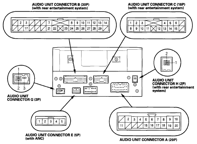 Courtesy of AMERICAN HONDA MOTOR CO., INC.
08-09 models without premium audio system/without navigation/6 CD type
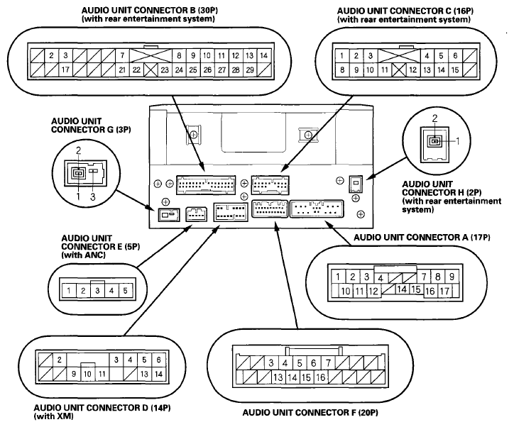 Courtesy of AMERICAN HONDA MOTOR CO., INC.
AUDIO UNIT CONNECTOR A (20P) ('07 model)
Courtesy of AMERICAN HONDA MOTOR CO., INC. AUDIO UNIT CONNECTOR REFERENCE
| Cavity |
Wire |
Connect to |
| A2 |
YEL/RED |
No. 32 (10 A) fuse in the driver's under-dash fuse/relay box (ACC) |
| A3 |
WHT |
Audio remote switch (AUDIO REMOTE) |
| A4 |
RED/WHT |
Rear controller and screen (SCTY3) |
| |
RED/BLU |
Multiplex integrated control unit (MICU) (SCTY1) |
| A5 |
PNK |
Right rear speaker+ (RR R SPKR+) |
| A6 |
BLU/WHT |
Left rear speaker+ (RR L SPKR+) |
| A7 |
GRN/YEL |
Front passenger's door speaker+ Right tweeter+ (FR R SPKR+) |
| A8 |
GRN/BLK |
Driver's door speaker+, Left tweeter+ (FR L SPKR+) |
| A9 |
RED/BLK |
No. 7 (7.5 A) fuse in the passenger's under-dash fuse/relay box (ILL+) |
| A10 |
WHT/GRN |
No. 5 (10 A) fuse in the driver's under-dash fuse/relay box (+B) |
| A11 |
BRN |
Remote switch ground (REMOTE GND) |
| A15 |
BLU/YEL |
Right rear speaker- (RR R SPKR-) |
| A16 |
BLU/BLK |
Left rear speaker- (RR L SPKR-) |
| A17 |
GRY/RED |
Front passenger's door speaker-, Right tweeter- (FR R SPKR-) |
| A18 |
LT GRN |
Driver's door speaker-, Left tweeter- (FR L SPKR-) |
| A19 |
RED |
Dash lights brightness controller (ILL-) |
| A20 |
BLK |
Body ground to G503 (GND) |
AUDIO UNIT CONNECTOR A (17P) ('08-10 models)
Courtesy of AMERICAN HONDA MOTOR CO., INC. AUDIO UNIT CONNECTOR REFERENCE
| Cavity |
Wire |
Connect to |
| A1 |
RED |
Dash lights brightness controller (ILL-) |
| A2 |
BLU/BLK |
Left rear speaker- (RR L SPKR-) |
| A3 |
LT GRN |
Driver's door speaker-, Left tweeter- (FR L SPKR-) |
| A4 |
RED/WHT |
Rear controller and screen (SCTY3) |
| RED/BLU |
Multiplex integrated control unit (MICU) (SCTY1) |
| A7 |
GRY/RED |
Front passenger's door speaker-. Right tweeter- (FR R SPKR-) |
| A8 |
BLU/YEL |
Right rear speaker- (RR R SPKR-) |
| A9 |
BLK |
Body ground to G503 (GND) |
| A10 |
RED/BLK |
No. 7 (7.5 A) fuse in the passenger's under-dash fuse/relay box (ILL+) |
| A11 |
BLU/WHT |
Left rear speaker+ (RR L SPKR+) |
| A12 |
GRN/BLK |
Driver's door speaker+, Left tweeter+ (FR L SPKR+) |
| A14 |
YEL/RED |
No. 32 (10 A) fuse in the driver's under-dash fuse/relay box (ACC) |
| A15 |
GRN/YEL |
Front passenger's door speaker+. Right tweeter+ (FR R SPKR+) |
| A16 |
PNK |
Right rear speaker+ (RR R SPKR+) |
| A17 |
WHT/GRN |
No. 5 (10 A) fuse in the driver's under-dash fuse/relay box (+B) |
AUDIO UNIT CONNECTOR B (30P) (With rear entertainment system
Courtesy of AMERICAN HONDA MOTOR CO., INC. AUDIO UNIT CONNECTOR REFERENCE
| Cavity |
Wire |
Connect to |
| B2 |
BLU |
Rear controller and screen (RR NTSC) |
| B3 |
GRY |
Shield for terminals No. 2 and No. 7 (RR NTSC SH) |
| B7 |
GRY |
Shield for terminals No. 21 and No. 22 (VIDE01 SH) |
| B8 |
BRN |
Auxiliary jack assembly (HP L OUT) |
| B9 |
GRY |
Shield for terminals No. 8, No. 24, and No. 25 (HP R/L OUT SH) |
| B10 |
GRY |
Shield for terminals No. 11, No. 12, and No. 13 (HPR/L SH) |
| B11 |
WHT |
Rear controller and screen (HPR/LGND) |
| B12 |
RED |
Rear controller and screen (HPL) |
| B13 |
BLK |
Rear controller and screen (HPR) |
| B14 |
YEL/RED |
Rear controller and screen (SYSTEM ACC) |
| B17 |
PNK |
Rear controller and screen (RR NTSC GND) |
| B21 |
LT BLU |
Auxiliary jack assembly (VIDE01 GND) |
| B22 |
PUR |
Auxiliary jack assembly (VIDE01) |
| B23 |
WHT/GRN |
Auxiliary jack assembly (COMN CHK) |
| B24 |
ORN |
Auxiliary jack assembly (HP R OUT) |
| B25 |
YEL |
Auxiliary jack assembly (HPR/L OUT GND) |
| B26 |
GRY |
Shield for terminals No. 27, No. 28, and No. 29 (VIDEO1 R/L SH) |
| B27 |
PNK |
Auxiliary jack assembly (VIDE01 R/L GND) |
| B28 |
GRN |
Auxiliary jack assembly (VIDE01 L) |
| B29 |
BLU |
Auxiliary jack assembly (VIDE01 R) |
AUDIO UNIT CONNECTOR C (16P) (With rear entertainment system)
Courtesy of AMERICAN HONDA MOTOR CO., INC. AUDIO UNIT CONNECTOR REFERENCE
| Cavity |
Wire |
Connect to |
| C1 |
WHT |
DVD player unit (DVD R/L GND) |
| C2 |
BLK |
DVD player unit (DVD L) |
| C3 |
RED |
DVD player unit (DVD R) |
| C4 |
GRY |
Shield for terminals No. 5 and No. 6 (DVD SH) |
| C5 |
PNK |
DVD player unit (DVD GND) |
| C6 |
BLU |
DVD player unit (DVD) |
| C8 |
GRY |
Shield for terminals No. 1, No. 2, and No. 3 (DVD R/L SH) |
| C9 |
LT BLU |
Rear controller and screen (GA-NET RR BUS+) |
| C10 |
GRY |
Shield for terminals No. 9 and No. 11 (GA-NET RR BUS SH) |
| C11 |
PUR |
Rear controller and screen (GA-NET RR BUS-) |
| C12 |
ORN |
DVD player unit (Rx) |
| C13 |
BRN |
DVD player unit (Tx) |
| C14 |
YEL |
DVD player unit (Tx/Rx GND) |
| C15 |
GRY |
Shield for terminals No. 12, No. 13, and No. 14 (Tx/Rx SH) |
AUDIO UNIT CONNECTOR D (14P) ('08-10 models with XM)
Courtesy of AMERICAN HONDA MOTOR CO., INC. AUDIO UNIT CONNECTOR REFERENCE
| Cavity |
Wire |
Connect to |
| D2 |
BLU/RED |
XM receiver (SYSTEM ACC) |
| D3 |
GRY |
Shield for terminals No. 9 and No. 10 (GA-NET AUDIO BUS2 SH) |
| D4 |
GRY |
Shield for terminals No. 5, No. 6, No. 13, and No. 14 (AUDIO 2 SH) |
| D5 |
RED |
XM receiver (AUDIO 2 R+) |
| D6 |
BLK |
XM receiver (AUDIO 2 L+) |
| D9 |
LT BLU |
XM receiver (GA-NET AUDIO BUS2+) |
| D10 |
PUR |
XM receiver (GA-NET AUDIO BUS2-) |
| D11 |
WHT/BLK |
XM receiver (GA-NET GND) |
| D13 |
WHT |
XM receiver (AUDIO 2 R-) |
| D14 |
GRN |
XM receiver (AUDIO 2 L-) |
AUDIO UNIT CONNECTOR E (5P) (With ANC)
Courtesy of AMERICAN HONDA MOTOR CO., INC. AUDIO UNIT CONNECTOR REFERENCE
| Cavity |
Wire |
Connect to |
| E1 |
BLK |
Active noise cancellation unit (ANC FR+) |
| E2 |
GRN |
Active noise cancellation unit (ANC FR-) |
| E3 |
RED |
Active noise cancellation unit (ANC RR+) |
| E4 |
WHT |
Active noise cancellation unit (ANC RR-) |
| E5 |
BRN |
Active noise cancellation unit (ANC CHK2) |
AUDIO UNIT CONNECTOR F (20P) ('08-10 models)
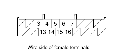 Courtesy of AMERICAN HONDA MOTOR CO., INC.
 AUDIO UNIT CONNECTOR REFERENCE
| Cavity |
Wire |
Connect to |
| F3 |
BLK |
Auxiliary jack assembly (AUX S GND) |
| F4 |
GRY |
Shield for terminals No. 3, No. 13, and No. 14 (AUX SH GND) |
| F5 |
LT GRN |
Auxiliary jack assembly (AUX GND) |
| F6 |
BRN |
Remote switches ground (REMOTE GND) |
| F7 |
WHT |
Audio remote switch (AUDIO REMOTE) |
| F13 |
WHT |
Auxiliary jack assembly (AUX L) |
| F14 |
RED |
Auxiliary jack assembly (AUX R) |
| F15 |
LT BLU |
Auxiliary jack assembly (AUX DET) |
| F16 |
YEL/GRN |
Active noise cancellation unit (SWD +B) |
AUDIO UNIT CONNECTOR G (3P)
Courtesy of AMERICAN HONDA MOTOR CO., INC. AUDIO UNIT CONNECTOR REFERENCE
| Cavity |
Wire |
Connect to |
| G1 |
- |
AM/FM antenna amplifier (SIG) |
| G2 |
- |
Shield for terminal No. 1 (SH (AM/FM)) |
| G3 |
- |
AM/FM antenna amplifier (ANT +B) |
AUDIO UNIT CONNECTOR H (2P) (With rear entertainment system)
Courtesy of AMERICAN HONDA MOTOR CO., INC. AUDIO UNIT CONNECTOR REFERENCE
| Cavity |
Wire |
Connect to |
| H1 |
- |
DVD player unit (DIGITAL SIG) |
| H2 |
- |
Shield for terminal No. 1 (DIGITAL SH) |
When replacing an audio unit connector, match the wires to the cavities listed in the following table.
'07 model without premium audio system/without navigation/1 CD type
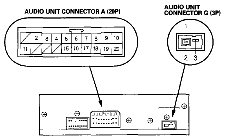 Courtesy of AMERICAN HONDA MOTOR CO., INC.
'08-10 models without premium audio system/without navigation/1 CD type
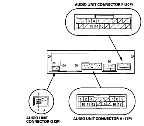 Courtesy of AMERICAN HONDA MOTOR CO., INC.
AUDIO UNIT CONNECTOR A (20P) ('07 model)
Courtesy of AMERICAN HONDA MOTOR CO., INC. AUDIO UNIT CONNECTOR REFERENCE
| Cavity |
Wire |
Connect to |
| A2 |
YEL/RED |
No. 32 (10 A) fuse in the driver's under-dash fuse/relay box (ACC) |
| A5 |
PNK |
Right rear speaker+ (RR R SPKR+) |
| A6 |
BLU/WHT |
Left rear speaker+ (RR L SPKR+) |
| A7 |
GRN/YEL |
Front passenger's door speaker+ (FR R SPKR+) |
| A8 |
GRN/BLK |
Driver's door speaker+, (FR L SPKR+) |
| A9 |
RED/BLK |
No. 7 (7.5 A) fuse in the passenger's under-dash fuse/relay box (ILL+) |
| A10 |
WHT/GRN |
No. 5 (10 A) fuse in the driver's under-dash fuse/relay box (+B) |
| A15 |
BLU/YEL |
Right rear speaker- (RR R SPKR-) |
| A16 |
BLU/BLK |
Left rear speaker- (RR L SPKR-) |
| A17 |
GRY/RED |
Front passenger's door speaker- (FR R SPKR-) |
| A18 |
LT GRN |
Driver's door speaker- (FR L SPKR-) |
| A19 |
RED |
Dash lights brightness controller (ILL-) |
| A20 |
BLK |
Body ground to G503 (GND) |
AUDIO UNIT CONNECTOR F (20P) ('08-10 models)
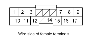 Courtesy of AMERICAN HONDA MOTOR CO., INC.
 AUDIO UNIT CONNECTOR REFERENCE
| Cavity |
Wire |
Connect to |
| F3 |
BLK |
Auxiliary jack assembly (AUX S GND) |
| F4 |
GRY |
Shield for terminals No. 3, No. 13, and No. 14 (AUX SH GND) |
| F5 |
LT GRN |
Auxiliary jack assembly (AUX GND) |
| F13 |
WHT |
Auxiliary jack assembly (AUX L) |
| F14 |
RED |
Auxiliary jack assembly (AUX R) |
| F15 |
LT BLU |
Auxiliary jack assembly (AUX DET) |
AUDIO UNIT CONNECTOR A (17P) ('08-10 models)
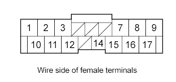 Courtesy of AMERICAN HONDA MOTOR CO., INC.
 AUDIO UNIT CONNECTOR REFERENCE
| Cavity |
Wire |
Connect to |
| A1 |
RED |
Dash lights brightness controller (ILL-) |
| A2 |
BLU/BLK |
Left rear speaker- (RR L SPKR-) |
| A3 |
LT GRN |
Driver's door speaker- (FR L SPKR-) |
| A7 |
GRY/RED |
Front passenger's door speaker-, Right tweeter- (FR R SPKR-) |
| A8 |
BLU/YEL |
Right rear speaker- (RR R SPKR-) |
| A9 |
BLK |
Body ground to G503 (GND) |
| A10 |
RED/BLK |
No. 7 (7.5 A) fuse in the passenger's under-dash fuse/relay box (ILL+) |
| A11 |
BLU/WHT |
Left rear speaker+ (RR L SPKR+) |
| A12 |
GRN/BLK |
Driver's door speaker+ (FR L SPKR+) |
| A14 |
YEL/RED |
No. 32 (10 A) fuse in the driver's under-dash fuse/relay box (ACC) |
| A15 |
GRN/YEL |
Front passenger's door speaker+ (FR R SPKR+) |
| A16 |
PNK |
Right rear speaker+ (RR R SPKR+) |
| A17 |
WHT/GRN |
No. 5 (10 A) fuse in the driver's under-dash fuse/relay box (+B) |
AUDIO UNIT CONNECTOR G (3P)
Courtesy of AMERICAN HONDA MOTOR CO., INC. AUDIO UNIT CONNECTOR REFERENCE
| Cavity |
Wire |
Connect to |
| G1 |
- |
AM/FM antenna amplifier (SIG) |
| G2 |
- |
Shield for terminal No. 1 (SH (AM/FM)) |
| G3 |
- |
AM/FM antenna amplifier (ANT +B) |