Intake Manifold Removal and Installation: Installation
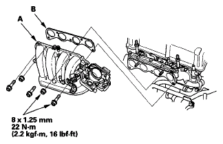
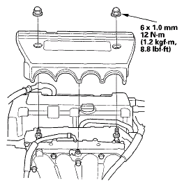
- Install the intake manifold (A) with a new gasket (B), and torque the bolts/nuts in a crisscross pattern in three steps, beginning with the inner bolt.
 Courtesy of AMERICAN HONDA MOTOR CO., INC.
- Raise the vehicle on the lift to full height.
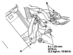
- Install the intake manifold bracket (A), then install the connectors (B).
 Courtesy of AMERICAN HONDA MOTOR CO., INC.
- Lower the vehicle on the lift.
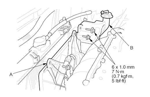
- Install the A/C condenser fan shroud (A), then install the coolant reservoir (B).
 Courtesy of AMERICAN HONDA MOTOR CO., INC.
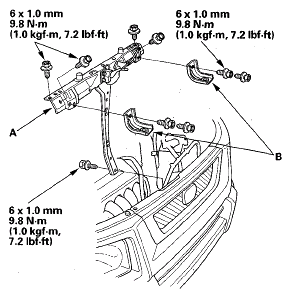
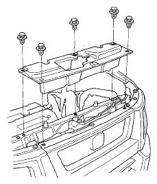
- Install the bulkhead (A), then install the upper bracket and cushions (B).
 Courtesy of AMERICAN HONDA MOTOR CO., INC.
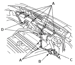
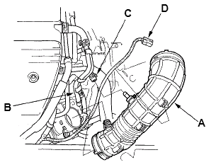
- Install the harness clamps (A), then connect the A/C compressor clutch connector (B), the engine coolant temperature (ECT) sensor 2 connector (C), and the fan motor connectors (D).
 Courtesy of AMERICAN HONDA MOTOR CO., INC.
- Install the front grille cover.
 Courtesy of AMERICAN HONDA MOTOR CO., INC.
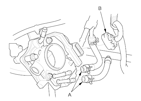
- Connect the water bypass hoses (A).
 Courtesy of AMERICAN HONDA MOTOR CO., INC.
- Connect the throttle actuator connector (B).
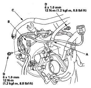
- Connect the evaporative emission (EVAP) canister hose (A), the manifold absolute pressure (MAP) sensor connector (B), and the brake booster vacuum hose (C).
 Courtesy of AMERICAN HONDA MOTOR CO., INC.
- Install the harness bracket mounting bolts (D).
 Courtesy of AMERICAN HONDA MOTOR CO., INC.
- Install the engine cover.
- Install the intake air duct (A), then connect the mass airflow (MAF) sensor/intake air temperature (IAT) sensor connector (B), and connect the vacuum hose (C) and breather pipe (D).
 Courtesy of AMERICAN HONDA MOTOR CO., INC.
- Clean up any spilled engine coolant.
- After installation, check that all tubes, hoses, and connectors are installed correctly.
- Refill the radiator with engine coolant, and bleed air from the cooling system with the heater valve open (see step 7 on COOLANT REPLACEMENT
).