Control Switch
- Push the horn button. If horn doesn't blow, horn circuit is defective. If horn blows, turn on the ignition switch and main switch, and push "SET" switch. Connect the positive probe of the voltmeter to terminal 6 and negative probe to terminal 9 at control unit connector. See Figure.
- If there is no voltage, and horn doesn't blow, there is a short circuit in the wiring harness from control switch to control unit. If there is no voltage and horn blows, push the "SET" switch.
- Connect the voltmeter positive probe to terminal 37, and the negative probe to ground. Read the voltage with the connector connected. If there is 12 volts, there is an open circuit in the wiring harness from slip ring to control unit.
- If in step 3) there was no voltage, remove steering wheel and check "SET" switch. If "SET" switch is okay, slip ring is defective. If voltmeter reads 12 volts, push the "RESUME" switch. Connect the voltmeter positive probe to terminal 11 and negative probe to terminal 9 of "RESUME" switch connector. See Figure.
- If there is no voltage, but horn blows, there is a short in the wiring harness from control switch to control unit. If there is no voltage and horn doesn't blow, push the "RESUME" switch. Connect the positive probe to terminal 38 and negative probe to ground on control unit connector.
- If there is 12 volts, there is an open circuit in the wiring harness from slip ring to control unit. If there is no voltage, remove the steering wheel and check the "RESUME" switch. If switch is okay, slip ring is defective.
- If in step 5) voltmeter reads 12 volts, check for continuity across terminals 11 and 6 at "RESUME" switch connector. If there is no continuity, circuit is okay. If there is continuity, disconnect slip ring connector and check for continuity between terminals 37 and 38 of control switch connector.
 Courtesy of AMERICAN HONDA MOTOR CO., INC.
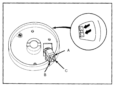
- If there is no continuity, wiring harness is shorted between slip ring and control unit. If there is continuity, check for continuity between terminals B and C of the control switch. See Fig 1. If there is no continuity, slip ring is defective. If there is continuity, control switch is defective.