Oil Pressure Indicator Illuminated With Engine Running
- Disconnect oil pressure switch connection. Oil pressure switch is located on front of engine behind exhaust manifold. Start engine. If indicator is illuminated, go to next step. If indicator is not illuminated, turn ignition switch to LOCK position. Using mechanical gauge, check engine oil pressure. If oil pressure is 4.5 psi or more, replace oil pressure switch. If pressure is less than 4.5 psi, problem exists in lubrication system.
- Turn ignition switch to LOCK position. Disconnect instrument cluster Gray 16-pin connector. Using an ohmmeter, check for continuity between instrument cluster Gray 16-pin connector terminal No. 8 (Yellow/Black wire) and ground. If continuity is present, repair short to ground in Yellow/Black wire. If continuity is not present, repair or replace instrument cluster printed circuit.
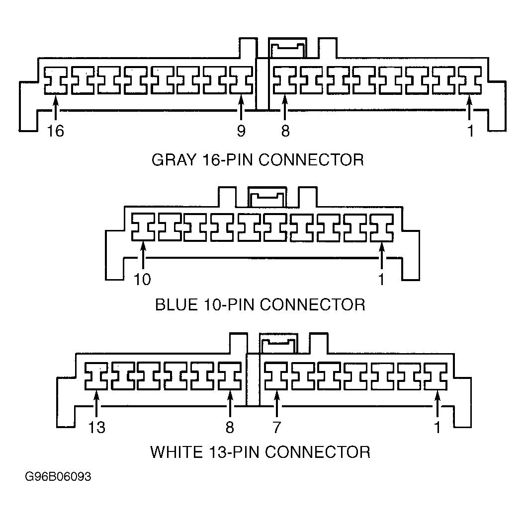
IDENTIFYING INSTRUMENT CLUSTER CONNECTOR TERMINALS
| Terminal No. (Wire Color) |
Function |
| Gray 16-Pin Connector |
| 1 (WHT/RED) |
Charge Indicator |
| 2 (BLK/WHT) |
IG-COIL METER Fuse Power |
| 4 (PPL/YEL) |
PCM MIL CHECK ENGINE Indicator |
| 6 (YEL/WHT) |
Engine Coolant Temperature (ECT) Sending Unit |
| 7 (ORG) |
Sensing & Diagnostic Module (SDM)/AIR BAG Indicator |
| 8 (YEL/BLK) |
Oil Pressure Switch/Oil Pressure Indicator |
| 9 (BRN) |
Igniter/Ignition Coil & Tachometer |
| 10 (BLU/YEL) |
ABS ACTIVE Indicator |
| 12 (BRN/BLK) |
Ignition Switch |
| 15 (RED/GRN) |
Illumination Controller/Illumination Lights |
| 16 (RED/YEL) |
Light Switch/Illumination Lights |
| Blue 10-Pin Connector |
| 7 (WHT/BLU) |
Left H/L Fuse/High Beam Indicator |
| 8 (RED) |
Dimmer Switch/High Beam Indicator |
| 9 (BLK) |
Ground |
| 10 (GRN/YEL) |
Combination Switch/Right Turn Indicator |
| White 13-Pin Connector |
| 1 (GRN/RED) |
Combination Switch/Left Turn Indicator |
| 2 (ORG/WHT) |
DRL Control Module/DRL Indicator |
| 3 (LT BLU) |
PCM/Up-Shift Indicator (M/T) |
| 4 (YEL/GRN) |
VSS Input/PCM (M/T) |
| 5 (RED/BLK) |
BRAKE Indicator |
| 7 (BLU/ORG) |
ABS Indicator Bulb Driver Relay |
| 8 (BLK) |
Ground |
| 9 (YEL/RED) |
Fuel Gauge Sending Unit/Fuel Gauge |
| 10 (BLK/BLU) |
Ground |
| 11 (BLK/WHT) |
IG-COIL METER Fuse Power |
| 12 (GRY/RED) |
Seat Belt Switch/Seat Belt Indicator |
| 13 (RED/WHT) |
Rear Defogger Switch/ Rear Defogger Indicator |