Installation Procedure
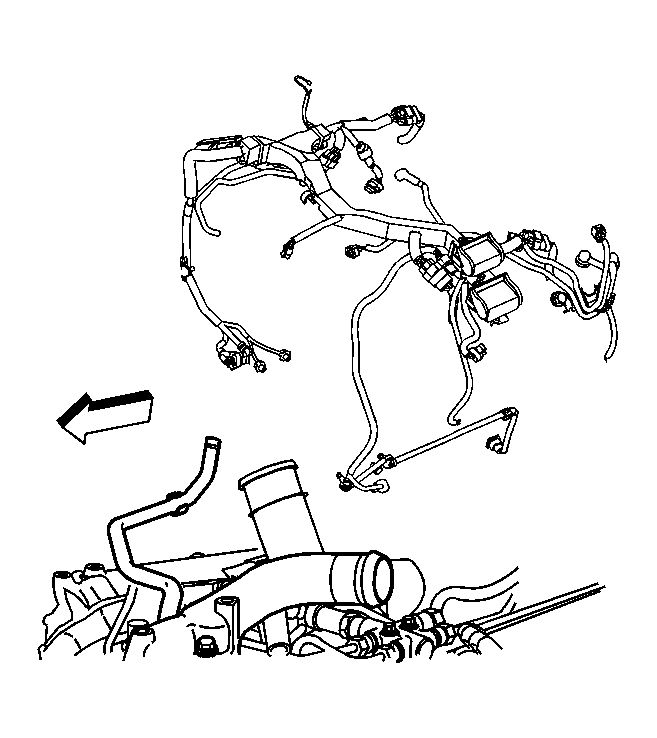 Courtesy of GENERAL MOTORS COMPANY
- Install engine wiring harness to vehicle.
 Courtesy of GENERAL MOTORS COMPANY
- Connect fuel rail pressure regulator connector.
- Route engine wiring harness to engine.
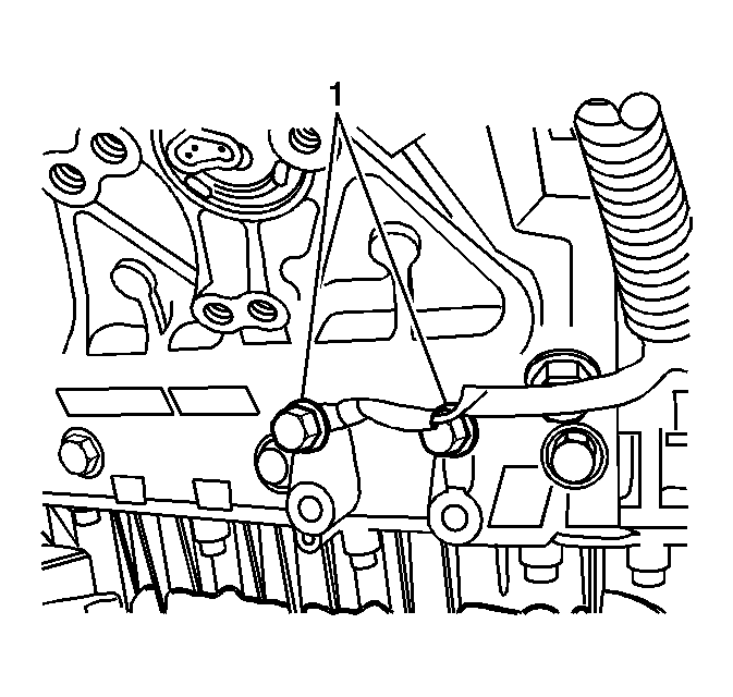 Courtesy of GENERAL MOTORS COMPANY
- Raise vehicle.
- Install bolts to retain engine wiring harness grounds.
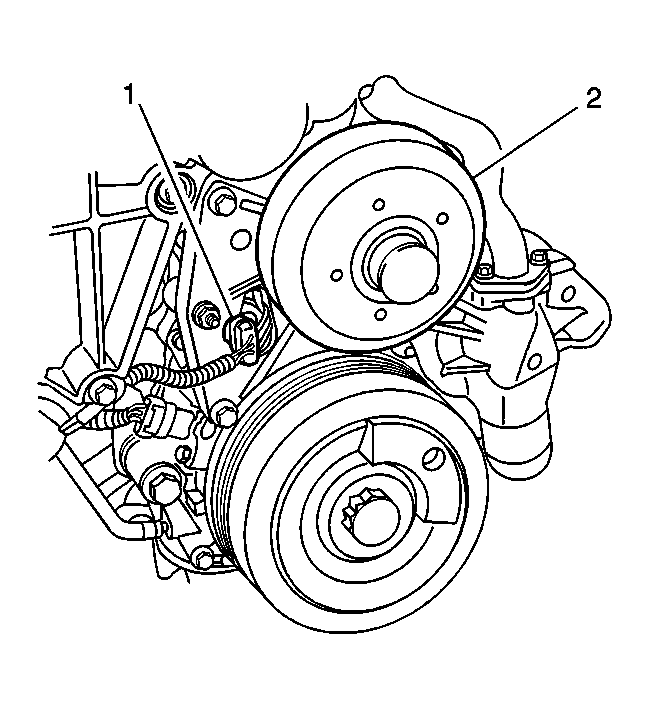 Courtesy of GENERAL MOTORS COMPANY
- Connect camshaft position sensor.
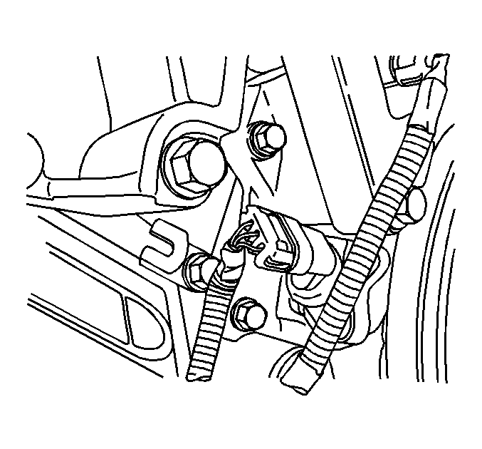 Courtesy of GENERAL MOTORS COMPANY
- Connect crankshaft position sensor.
- Install front lower skid plate.
- Lower vehicle.
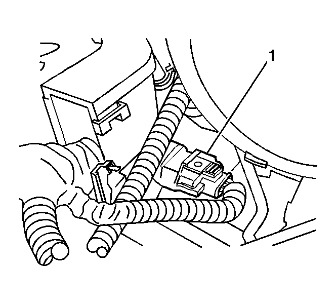 Courtesy of GENERAL MOTORS COMPANY
- Connect fuel rail pressure sensor connector.
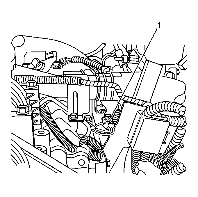 Courtesy of GENERAL MOTORS COMPANY
- Connect BARO sensor connector.
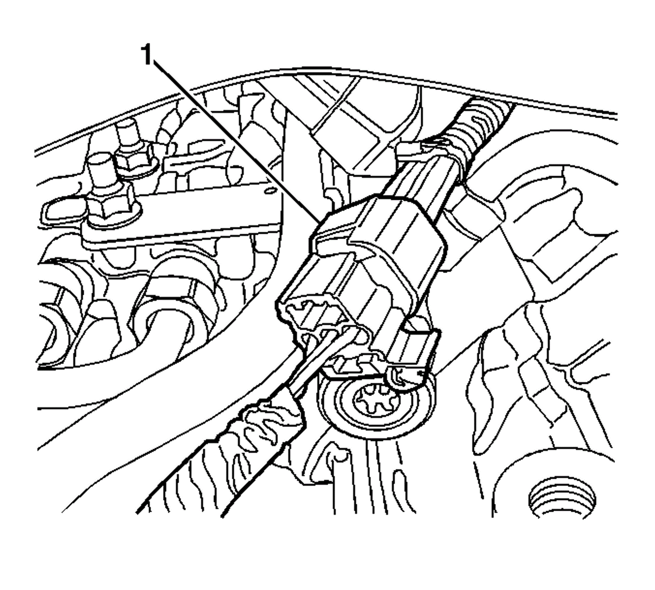 Courtesy of GENERAL MOTORS COMPANY
- Connect oil level sensor harness connector.
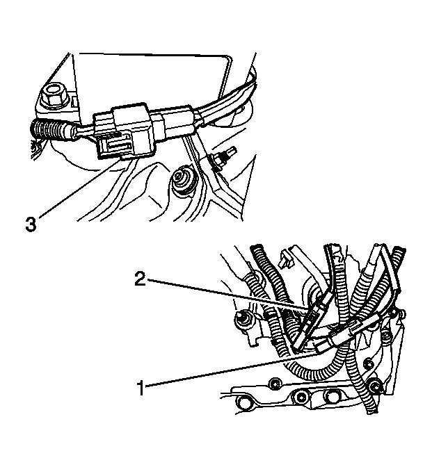 Courtesy of GENERAL MOTORS COMPANY
- Connect glow plug relay connectors.
 Courtesy of GENERAL MOTORS COMPANY
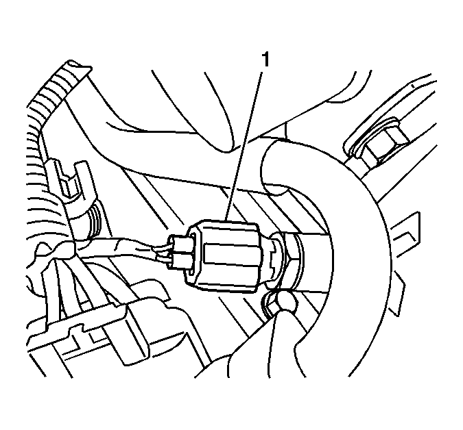
- Connect fuel rail temperature sensor harness connector.
 Courtesy of GENERAL MOTORS COMPANY
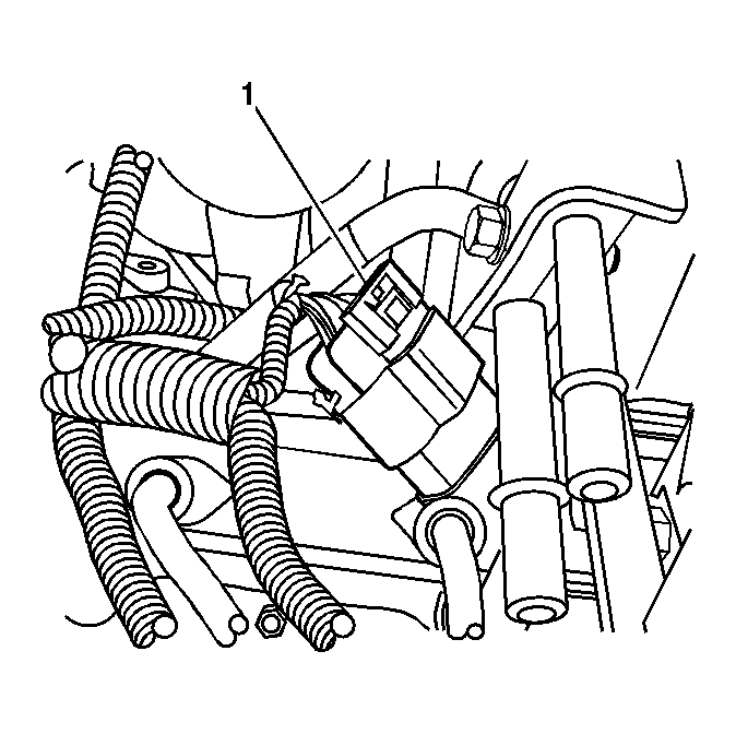
- Connect left rear fuel injector harness connector.
 Courtesy of GENERAL MOTORS COMPANY
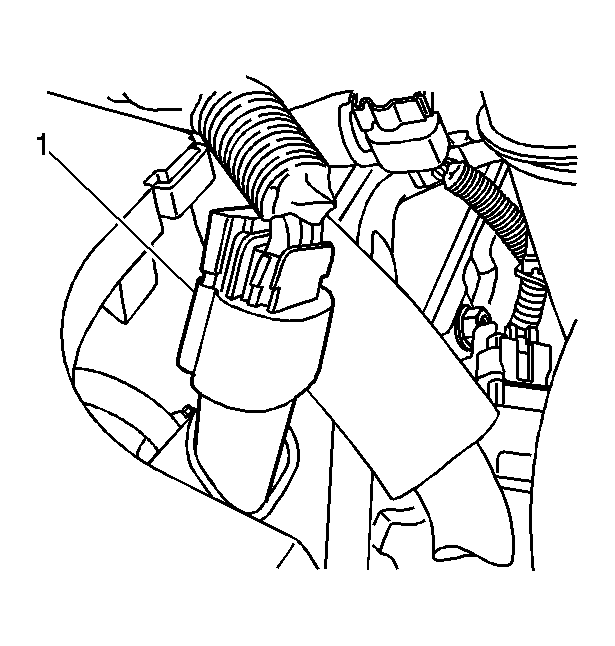
- Connect left front fuel injector harness connector.
 Courtesy of GENERAL MOTORS COMPANY
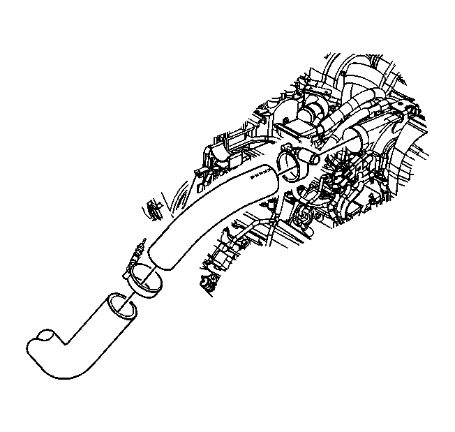
- Install left turbo air outlet hose.
 Courtesy of GENERAL MOTORS COMPANY
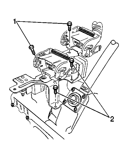
- Install bolts to retain bulk connectors to bracket.
 Courtesy of GENERAL MOTORS COMPANY
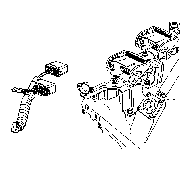
- Connect engine harness bulk connectors.
 Courtesy of GENERAL MOTORS COMPANY
- Install turbo water inlet hose.
 Courtesy of GENERAL MOTORS COMPANY
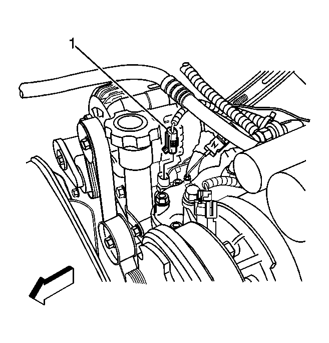
- Connect coolant temperature sensor.
 Courtesy of GENERAL MOTORS COMPANY
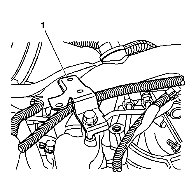
- Install engine sight shield hold-down bracket.
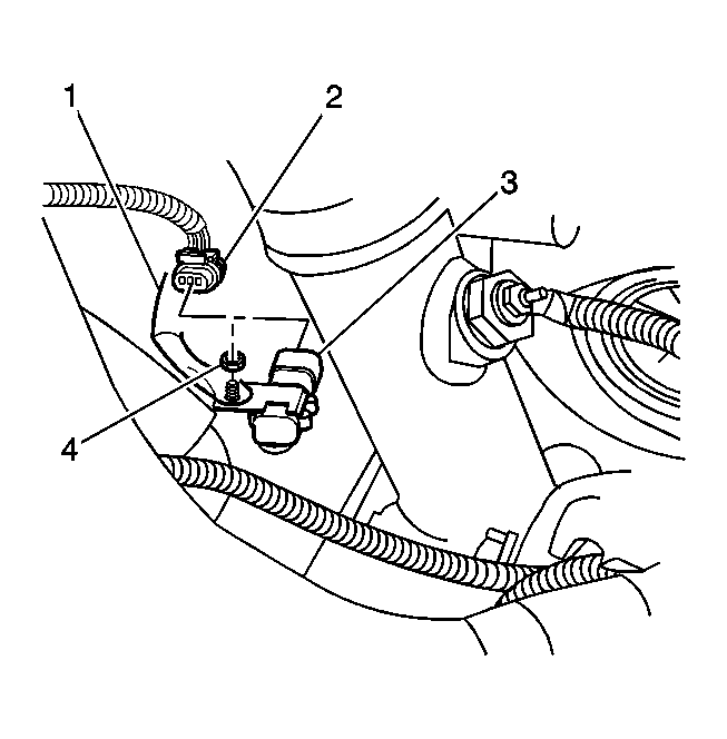 Courtesy of GENERAL MOTORS COMPANY
- Connect turbo boost sensor.
 Courtesy of GENERAL MOTORS COMPANY
- Connect right front fuel injector harness connector.
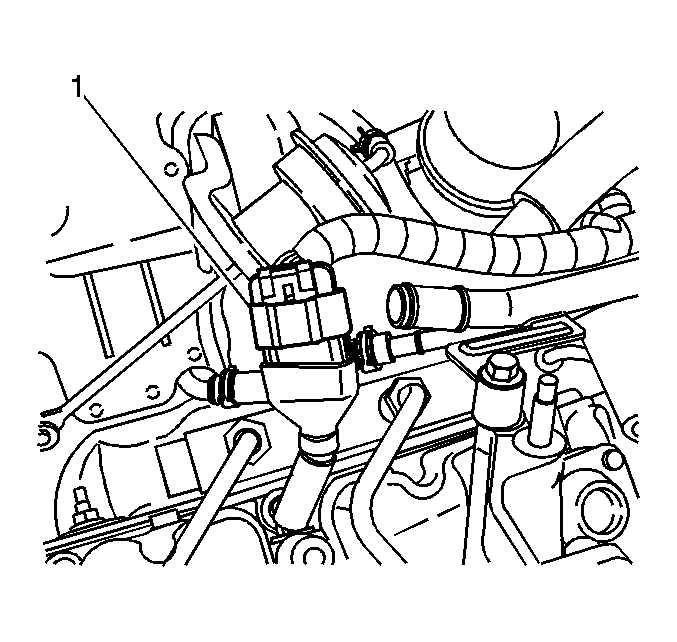 Courtesy of GENERAL MOTORS COMPANY
- Connect right rear fuel injector harness connector.
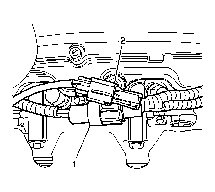 Courtesy of GENERAL MOTORS COMPANY
- Connect fuel filter/heater assembly connectors.
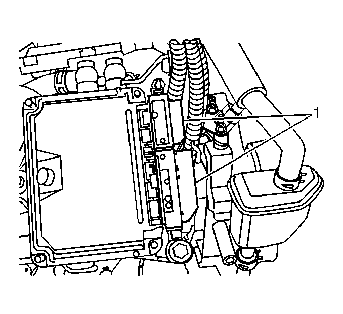 Courtesy of GENERAL MOTORS COMPANY
- Connect fuel injection control module.
- Install air intake duct. Refer to Air Cleaner Inlet Duct Replacement .
- Install engine sight shield.
- Connect negative battery cable. Refer to Battery Negative Cable Disconnection and Connection (Auxiliary Battery)
, Battery Negative Cable Disconnection and Connection (Single Battery)
in Engine Electrical.