Alternators & Regulators - DELCO-REMY With Integral Regulator: Overhaul: Reassembly
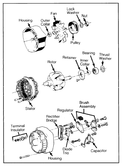
- Fill cavity between retainer plate and bearing 1/4 full with lubricant (Delco-Remy 1948791 or equivalent). Assemble bearing and slinger (flat washer on some models) in front housing. Press bearing in with collar that fits over outer race. If bearing retainer plate felt seal is hardened, replace retainer plate.
- Install retainer plate and screws. Press rotor into end frame. Assemble collar, fan, pulley, washer and nut.
- If rear bearing was removed, support inside of rear housing with hollow cylinder. On 10SI and 27SI models, place flat plate over bearing. Press bearing into housing from outside, until bearing is flush with end frame. On 15SI models, use thin wall tube in space between grease cup and housing to push bearing in until flush with housing. Oil lip of replacement bearing seal, and press seal in with lip away from bearing.
- Install springs and brushes in brush holder. Install wooden toothpick in hole at bottom of holder to retain brushes. Install voltage regulator. Attach brush holder into rear housing, noting stack-up of parts. Allow toothpick to protrude through hole in rear housing.
 Courtesy of GENERAL MOTORS COMPANY
- Install diode trio lead strap attaching screw and washer. Tighten brush holder screws. Position bridge rectifier on rear housing with insulator between heat sink and rear housing.
- Install bridge rectifier and battery terminal screws. Connect capacitor lead to bridge rectifier. Position diode trio on end housing. Install diode trio lead clip screw, making sure insulating washer is over top of diode connector.
- Install stator on rear housing. Attach stator leads to bridge rectifier terminals. Remove tape covering bearing and join front and rear housings with scribe marks aligned. Install through bolts and tighten. Remove toothpick from brush holder assembly.
ALTERNATOR OUTPUT
| Stamped Amperage |
Amperage @14V |
Rated Output (Engine RPM) |
| 37 |
22 |
2000 |
| 42 |
25 |
2000 |
| 55 |
30 |
2000 |
| 61 |
30 |
2000 |
| 63 |
32 |
2000 |
| 70 |
55 |
2000 |
| 80 |
55 |
2000 |
| 85 |
|
|