Pinpoint Test Q: An Individual Button Or Feature Is Inoperative From The RKE Transmitter
- Q1 VERIFY THE DOOR LOCK OPERATION
- Press the lock and unlock button on the door lock control switch while observing the door lock operation.
- Do the door locks operate correctly?
- Q2 VERIFY THE HORN OPERATION
- Using a scan tool, view the BCM PIDs.
- Select the BCM horn PID (HORN) and active command the horn on then off.
- Does the horn sound when commanded on?
- Yes
: GO to Q3.
- No
: REFER to
HORN
.
- Q3 VERIFY THE HAZARD LAMP OPERATION
- Activate the hazard flasher lamp function.
- Do the hazard lamps operate correctly?
- Q4 VERIFY THE LUGGAGE COMPARTMENT LID RELEASE OPERATION
- Unlock the doors using the door lock control switch.
- Press the luggage compartment lid release button.
- Does the luggage compartment lid latch release?
- Q5 VERIFY THE REMOTE START BUTTON INPUT
- Using a scan tool, view the BCM PIDs.
- Monitor the BCM LST_RKE_xMTR PID while pressing the remote start button on the suspect IKT.
- Does the PID indicate the remote start button is being pressed?
- Q6 CHECK THE BCM FOR THE RKE TRANSMITTER SIGNAL
- Ignition ON.
- Using a scan tool, view the BCM PIDs.
- Using a scan tool, monitor the BCM LST_RKE_xMTR PID while pressing the luggage compartment lid release button on the suspect RKE transmitter.
- Does the PID indicate the luggage compartment lid release button is being pressed?
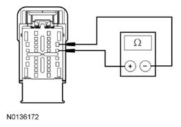
- Q7 CHECK THE BCM FOR THE LUGGAGE COMPARTMENT LID RELEASE OUTPUT CIRCUIT FOR AN OPEN
- Ignition OFF.
- Disconnect: BCM C2280D.
- Ignition ON.
- Measure the resistance between the BCM C2280D-28, circuit CPL80 (WH/GN), harness side and the BCM C2280D-29, circuit CPL84 (GN/BN), harness side.
 Courtesy of FORD MOTOR CO.
- Is the resistance less than 3 ohms?
- Yes
: GO to Q8.
- No
: REPAIR the circuit.
- Q8 CHECK FOR CORRECT BCM OPERATION
- Disconnect and inspect all the BCM connectors.
- Repair:
- corrosion (install new connector or terminals - clean module pins)
- damaged or bent pins - install new terminals/pins
- pushed-out pins - install new pins as necessary
- Reconnect the BCM connectors. Make sure they seat and latch correctly.
- Operate the system and determine if the concern is still present.
- Is the concern still present?
- Yes
: CHECK On-Line Automotive Service Information System (OASIS) for any applicable TSBs. If a TSB exists for this concern, DISCONTINUE this test and FOLLOW TSB instructions. If no TSBs address this concern, INSTALL a new BCM. REFER to
MULTIFUNCTION ELECTRONIC MODULES
.
- No
: The system is operating correctly at this time. The concern may have been caused by module connections. ADDRESS the root cause of any connector or pin issues.