- Install the hollow input shaft onto the solid input shaft.
NOTE:
Make sure not to damage the inner input shaft seal or bearing.
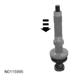 Courtesy of FORD MOTOR CO.
- Install output shaft 2 on the special tool.
NOTE:
Make sure the synchronizers are in the neutral position.
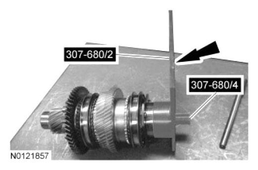 Courtesy of FORD MOTOR CO.
- Install the input shaft on the special tool.
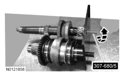 Courtesy of FORD MOTOR CO.
- Install output shaft 1 on the special tool.
NOTE:
Make sure the synchronizers are in the neutral position.
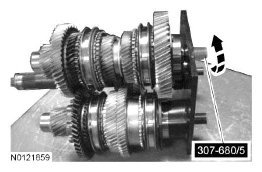 Courtesy of FORD MOTOR CO.
- Install the special tool.
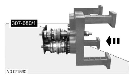 Courtesy of FORD MOTOR CO.
- Flip the gearset assembly over onto the special tool.
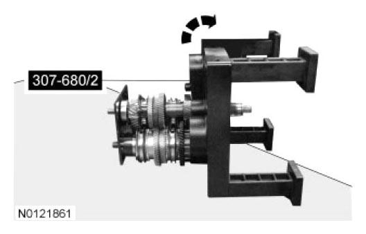 Courtesy of FORD MOTOR CO.
- Remove the special tool.
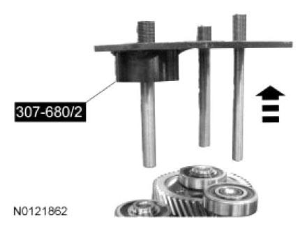 Courtesy of FORD MOTOR CO.
- Install the 4th/reverse shift fork.
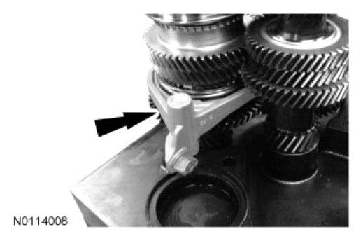 Courtesy of FORD MOTOR CO.
- Install the 2nd/6th gear shift fork and linkage.
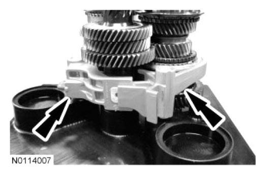 Courtesy of FORD MOTOR CO.
- Install shift drum 1.
NOTE:
Make sure the shift drum is in the neutral position as shown in illustration.
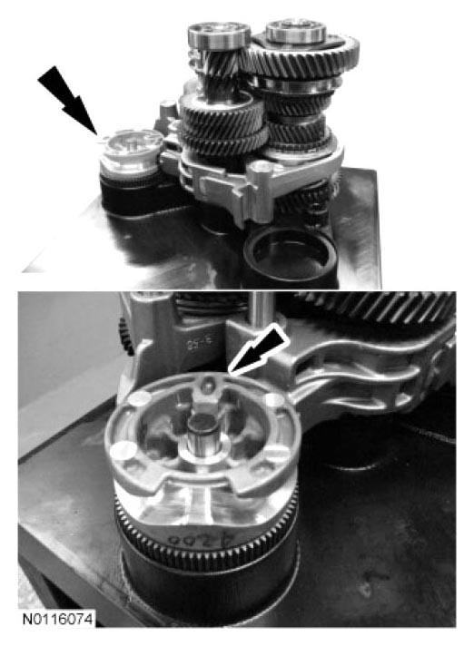 Courtesy of FORD MOTOR CO.
- Install the 3rd gear linkage and shift drum 2.
NOTE:
Make sure the shift drum is in the neutral position as shown in illustration.
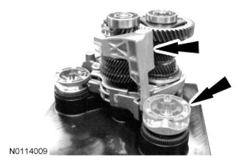 Courtesy of FORD MOTOR CO.
- Install the 1st/5th gearshift fork
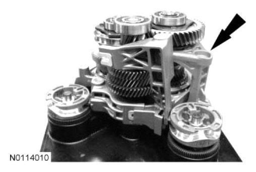 Courtesy of FORD MOTOR CO.
- Install the 3rd gear shift fork.
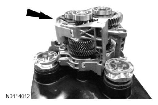 Courtesy of FORD MOTOR CO.
- Install the shift fork shafts.
- Install the small shift fork shafts.
- Install the large shift fork shafts.
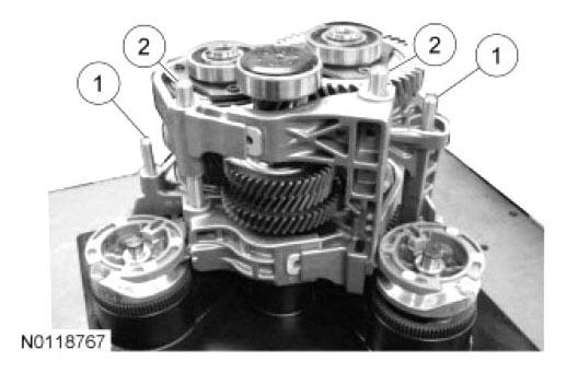 Courtesy of FORD MOTOR CO.
- Install the oil spout.
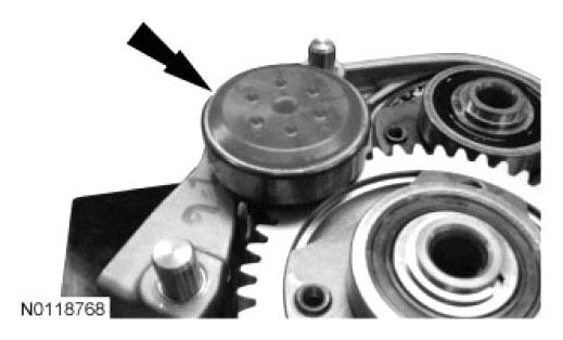 Courtesy of FORD MOTOR CO.
- Install the special tools.
NOTE:
Make sure the bearing retainer brackets are positioned as shown in illustration.
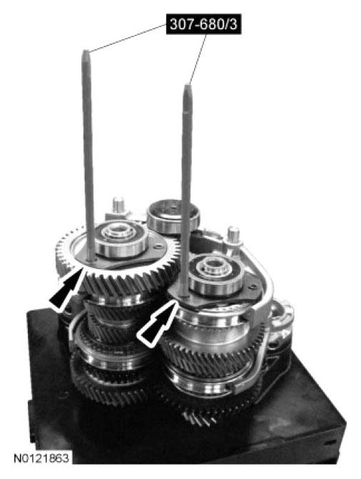 Courtesy of FORD MOTOR CO.
- Install the transaxle case onto the gearset assemblies.
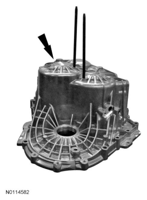 Courtesy of FORD MOTOR CO.
- Install the 6 bearing retainer bolts.
- Tighten to 32 Nm (24 lb-ft).
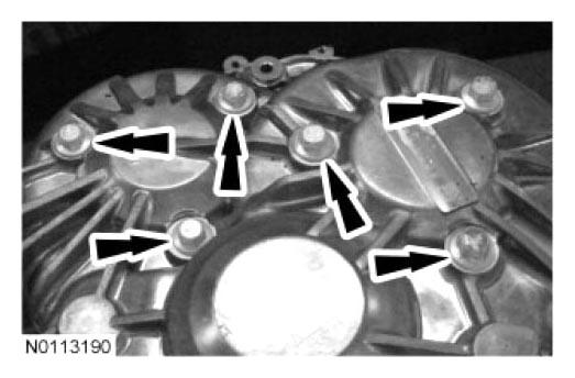 Courtesy of FORD MOTOR CO.
- Install the special tool.
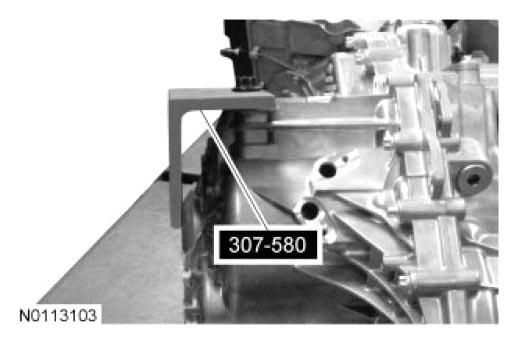 Courtesy of FORD MOTOR CO.
- Flip the transaxle case assembly over onto the special tool.
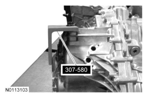 Courtesy of FORD MOTOR CO.
- Remove the special tool.
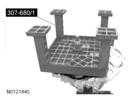 Courtesy of FORD MOTOR CO.
- Install the magnet.
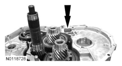 Courtesy of FORD MOTOR CO.
- Install the small clock gears and pins.
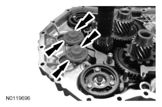 Courtesy of FORD MOTOR CO.
- Install the large clock gears and pins.
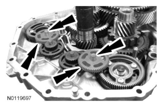 Courtesy of FORD MOTOR CO.
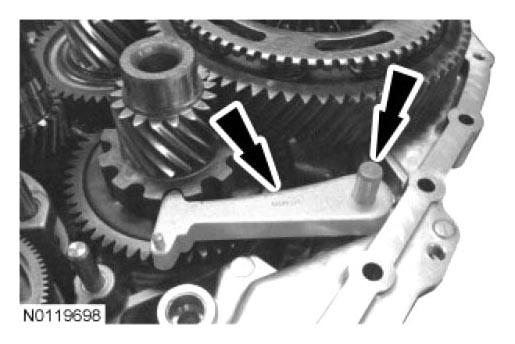
- Install the park pawl and park pawl rod.
 Courtesy of FORD MOTOR CO.
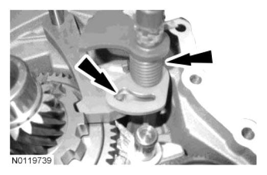
- Install the park pawl actuation shaft assembly.
NOTE:
Make sure the pin is installed as shown in illustration.
 Courtesy of FORD MOTOR CO.
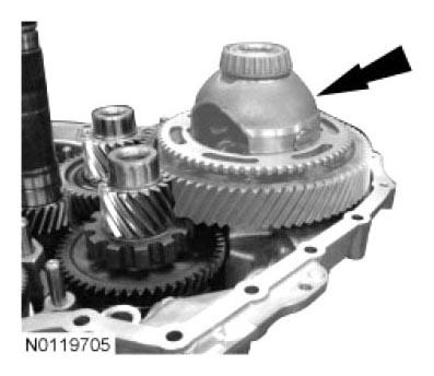
- Install the differential.
NOTE:
If the differential bearings, differential, clutch housing and/or transaxle case are replaced refer to DIFFERENTIAL SHIM SELECTION in this information.
 Courtesy of FORD MOTOR CO.
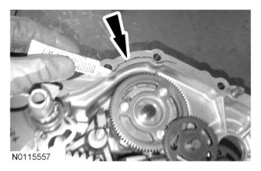
- Apply a 1 mm (0.039 in) bead of sealant around the inside of the bolt holes on the case side.
NOTE:
Make sure the transaxle case and the clutch housing are clean and no old sealant is present or transmission fluid leaks can occur and cause transaxle damage.
 Courtesy of FORD MOTOR CO.
- Using a 1500W heat gun, or equivalent, heat the input shaft bearing in the clutch housing for approximately 5 minutes.
NOTE:
Do not overheat the bearing or damage to the bearing may occur.
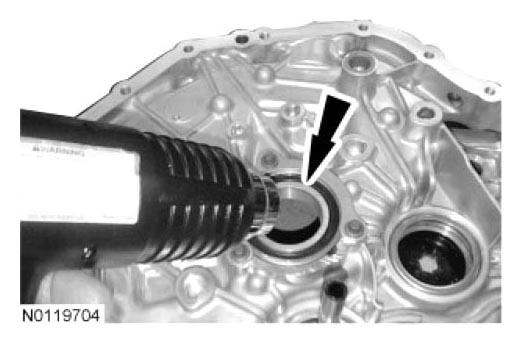 Courtesy of FORD MOTOR CO.
- Install the clutch housing.
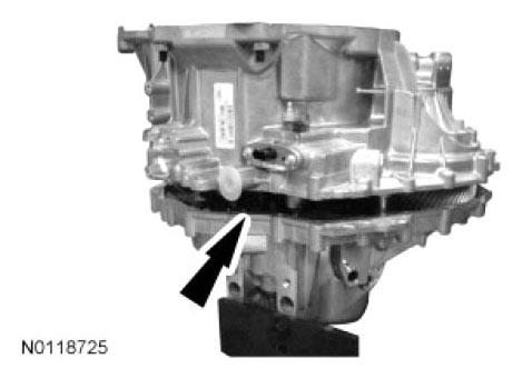 Courtesy of FORD MOTOR CO.
- Install the 18 bottom clutch housing-to-case bolts (14 shown in illustration).
- Tighten to 27 Nm (20 lb-ft).
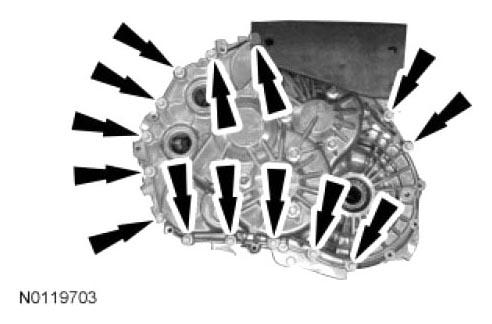 Courtesy of FORD MOTOR CO.
- Install the 3 top clutch housing-to-case bolts.
- Tighten to 27 Nm (20 lb-ft).
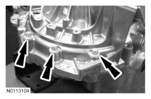 Courtesy of FORD MOTOR CO.
- Install the park plunger.
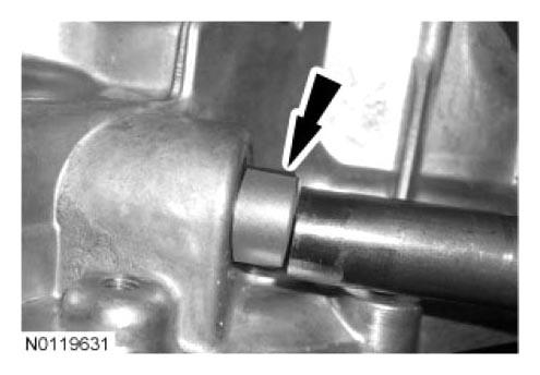 Courtesy of FORD MOTOR CO.
- Install the park plunger plug.
- Tighten to 43 Nm (32 lb-ft).
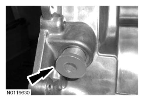 Courtesy of FORD MOTOR CO.
- Install a new input shaft snap ring.
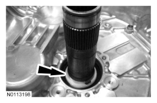 Courtesy of FORD MOTOR CO.
- Using the special tools, install a new input shaft seal.
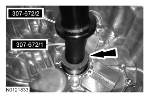 Courtesy of FORD MOTOR CO.
- Using the locating flange on the guide tube, install the guide tube.
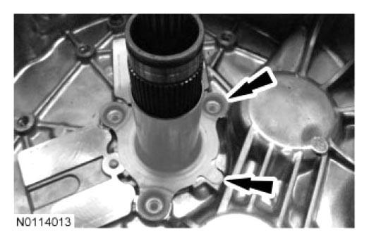 Courtesy of FORD MOTOR CO.
- Install the guide tube bolts.
NOTE:
The guide tube bolts must not project beyond the mounting surface of the clutch engagement levers.
- Tighten to 8 Nm (71 lb-in).
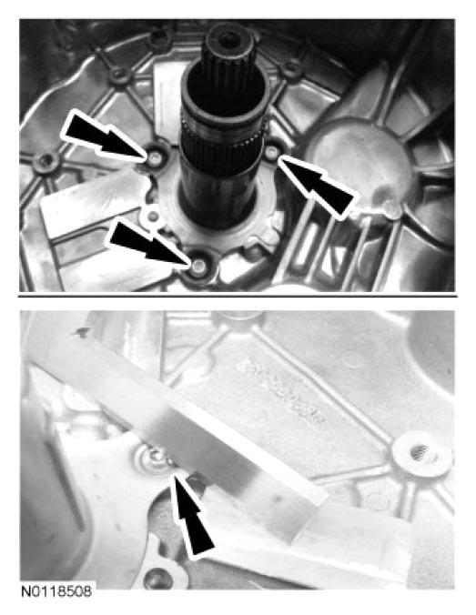 Courtesy of FORD MOTOR CO.
- Install the clutch engagement system. For additional information, refer to CLUTCH ENGAGEMENT SYSTEM in this information.
- Install the clutch. For additional information, refer to CLUTCH in this information.
- Install the OSS
sensor. For additional information, refer to OUTPUT SHAFT SPEED (OSS) SENSOR in this information.
- Install the input shaft speed sensors. For additional information, refer to INPUT SHAFT SPEED SENSOR - NO. 1 and INPUT SHAFT SPEED SENSOR - NO. 2 in this information.
- Install the TR
sensor. For additional information, refer to TRANSMISSION RANGE (TR) SENSOR in this information.
- Install the transaxle into the vehicle. For additional information, refer to TRANSAXLE in this information.
- Perform the TCM
Adaptive Learning procedure. Refer to TRANSMISSION CONTROL MODULE (TCM) ADAPTIVE LEARNING in this information.
- Perform the Clutch Adaptive Learning procedure. Refer to CLUTCH ADAPTIVE LEARNING in this information.