Pinpoint Test
- CHECK AND CLEAN THE REAR VIDEO CAMERA LENS
- Clean and make sure the rear video camera lens is clear of any debris.
- Test the video camera system and verify the video camera image.
- Is the video camera concern still present?
- Yes:
GO to 2
on page 2.
- No:
The system is operating correctly at this time. The concern was caused by a dirty video camera lens.
- CHECK THE VIDEO CAMERA (+) AND (-) SIGNAL CIRCUITS INTEGRITY
- Ignition OFF.
- Disconnect: Accessory Protocol Interface Module (APIM).
- Measure:
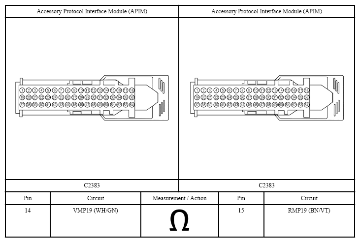 Courtesy of FORD MOTOR CO.
- Is the resistance between 74 and 106 ohms?
- Yes:
GO to 3
on page 2.
- No:
GO to 6 on page 4.
- CHECK THE VIDEO CAMERA GROUND CIRCUIT FOR AN OPEN
- Disconnect: Video Camera.
- Measure:
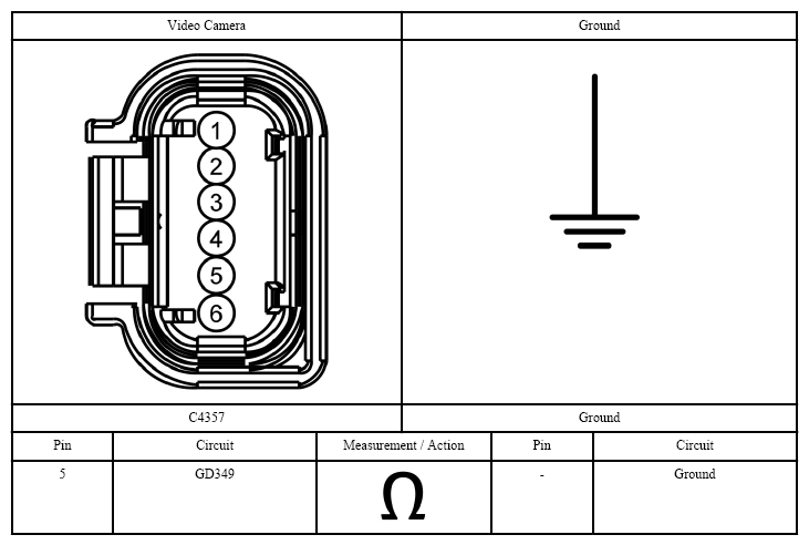 Courtesy of FORD MOTOR CO.
- Is the resistance less than 3 ohms?
- Yes:
GO to 4
on page 3.
- No:
REPAIR the circuit.
- CHECK THE VIDEO CAMERA (+) AND (-) SIGNAL CIRCUITS FOR A SHORT TO GROUND
- Measure:
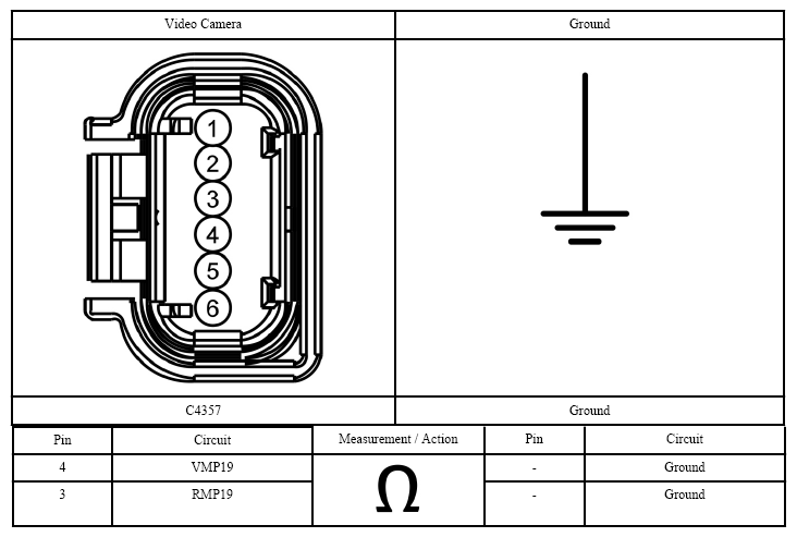 Courtesy of FORD MOTOR CO.
- Are the resistances greater than 10,000 ohms?
- Yes:
GO to 5
on page 4.
- No:
REPAIR the circuit in question.
- CHECK THE VIDEO CAMERA (+) AND (-) SIGNAL CIRCUITS FOR A SHORT TO THE VIDEO SHIELD
- Measure:
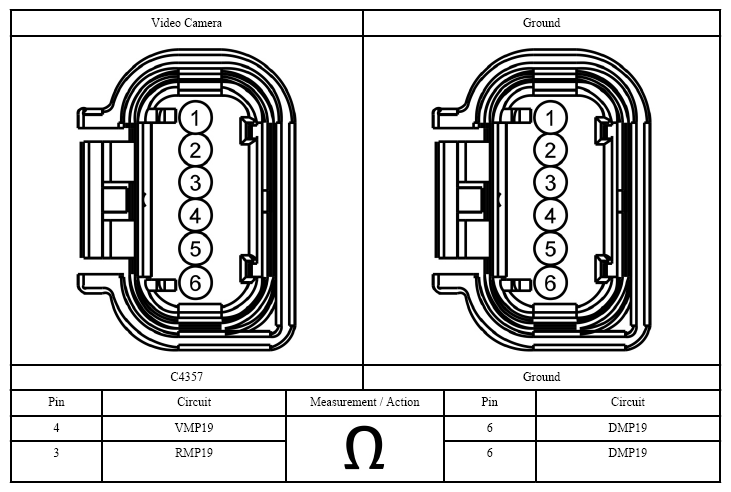 Courtesy of FORD MOTOR CO.
- Are the resistances greater than 10,000 ohms?
- Yes:
GO to 9 on page 7.
- No:
REPAIR the circuit in question.
- CHECK THE VIDEO CAMERA (+) AND (-) SIGNAL CIRCUITS FOR AN OPEN
- Connect a fused jumper wire:
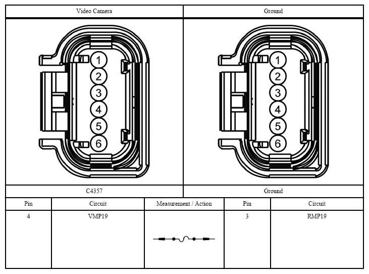 Courtesy of FORD MOTOR CO.
- Measure:
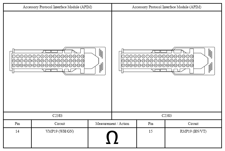 Courtesy of FORD MOTOR CO.
- Is the resistance less than 3 ohms?
- Yes:
REMOVE the jumper wire. GO to 8 on page 6.
- No:
REMOVE the jumper wire. GO to 7
on page 6.
- CHECK THE VIDEO CAMERA (+) SIGNAL CIRCUIT FOR AN OPEN
- Measure:
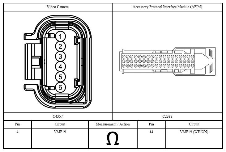 Courtesy of FORD MOTOR CO.
- Is the resistance less than 3 ohms?
- Yes:
REPAIR the video (-) signal circuit.
- No:
REPAIR the video (+) signal circuit.
- CHECK THE SHIELD CIRCUIT FOR AN OPEN
- Disconnect: In-line C211.
- Measure:
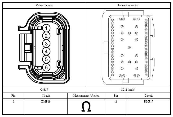 Courtesy of FORD MOTOR CO.
- Is the resistance less than 3 ohms?
- Yes:
GO to 9
on page 7.
- No:
REPAIR the circuit.
- CHECK FOR CORRECT VIDEO CAMERA OPERATION
- Disconnect the video camera connector.
- Check for:
- corrosion (install new connector or terminals - clean module pins)
- damaged or bent pins - install new terminals/pins
- pushed-out pins - install new pins as necessary
- Reconnect the video camera connector. Make sure it seats and latches correctly.
- Operate the system and determine if the concern is still present.
- Is the concern still present?
- Yes:
INSTALL a new video camera. REFER to Video Camera .
- No:
The system is operating correctly at this time. The concern may have been caused by the video camera connection. ADDRESS the root cause of any connector or pin issues.