Pinpoint Test
- CHECK THE Head Up Display (HUD) MODULE Diagnostic Trouble Codes (DTCs)
- Ignition ON.
- Using a scan tool, perform the Head Up Display (HUD) module self-test.
- Clear the Diagnostic Trouble Codes (DTCs).
- Repeat the Head Up Display (HUD) module self-test.
- Is Diagnostic Trouble Code (DTC) U3003:16 still present?
- Yes:
GO to step 2
.
- No:
The system is operating correctly at this time. The Diagnostic Trouble Code (DTC) may have been set due to a previous low battery voltage condition.
- CHECK FOR CHARGING SYSTEM Diagnostic Trouble Codes (DTCs) IN THE Powertrain Control Module (PCM)
- Using a scan tool, perform the Powertrain Control Module (PCM) Key ON Engine OFF (KOEO) self-test.
- Is Diagnostic Trouble Code (DTC) P0562, P0620, P0622, P0625, P0626 or P065B set in the Powertrain Control Module (PCM)?
- CHECK THE BATTERY CONDITION AND STATE OF CHARGE
- Check the battery condition and verify the battery is fully charged. REFER to DIAGNOSTIC ROUTINE A .
- Is the battery OK and fully charged?
- CHECK THE Head Up Display (HUD) MODULE VOLTAGE SUPPLY
- Ignition OFF.
- Measure and record the voltage at the battery.
- Disconnect: Head Up Display (HUD) Module.
- Ignition ON.
- Measure:
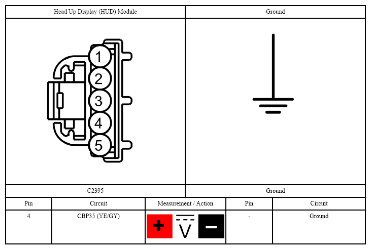 Courtesy of FORD MOTOR CO.
- Is the voltage within 0.2 volt of the recorded battery voltage?
- Yes:
GO to step 5
.
- No:
REPAIR the circuit.
- CHECK THE Head Up Display (HUD) MODULE GROUND CIRCUIT
- Measure:
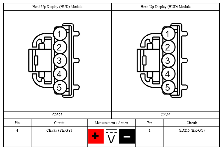 Courtesy of FORD MOTOR CO.
- Is the voltage within 0.2 volt of the recorded battery voltage?
- Yes:
GO to step 6
.
- No:
REPAIR the circuit.
- CHECK FOR CORRECT Head Up Display (HUD) MODULE OPERATION
- Disconnect and inspect the Head Up Display (HUD) module connector.
- Repair:
- corrosion (install new connector or terminals - clean module pins)
- damaged pins - install new terminals/pins
- pushed-out pins - install new pins as necessary
- Reconnect the Head Up Display (HUD) module connector. Make sure it seats and latches correctly.
- Operate the system and determine if the concern is still present.
- Is the concern still present?
- Yes:
CHECK On-Line Automotive Service Information System (OASIS) for any applicable Technical Service Bulletins (TSBs). If a Technical Service Bulletin (TSB) exists for this concern, DISCONTINUE this test and FOLLOW Technical Service Bulletin (TSB) instructions. If no Technical Service Bulletins (TSBs) address this concern, INSTALL a new Head Up Display (HUD) module. REFER to HEAD UP DISPLAY (HUD) MODULE . TEST the system for normal operation.
- No:
The system is operating correctly at this time. The concern may have been caused by module connections. ADDRESS the root cause of any connector or pin issues.