Pinpoint Test
- CHECK THE Diagnostic Trouble Codes (DTCs) FROM THE CONTINUOUS AND ON-DEMAND Head Up Display (HUD) MODULE SELF-TESTS
- Using a scan tool, perform the Head Up Display (HUD) module self-test.
- Are any Head Up Display (HUD) module Diagnostic Trouble Codes (DTCs) recorded?
- CHECK THE Cruise-Control Module (C-CM) Diagnostic Trouble Codes (DTCs)
- Using a scan tool, perform the Cruise-Control Module (C-CM) self-test.
- Are any Cruise-Control Module (C-CM) Diagnostic Trouble Codes (DTCs) recorded?
- CHECK THE MESSAGE CENTER FOR CORRECT OPERATION
- Check the Instrument Panel Cluster (IPC) message center for correct operation.
- Does the message center operate correctly?
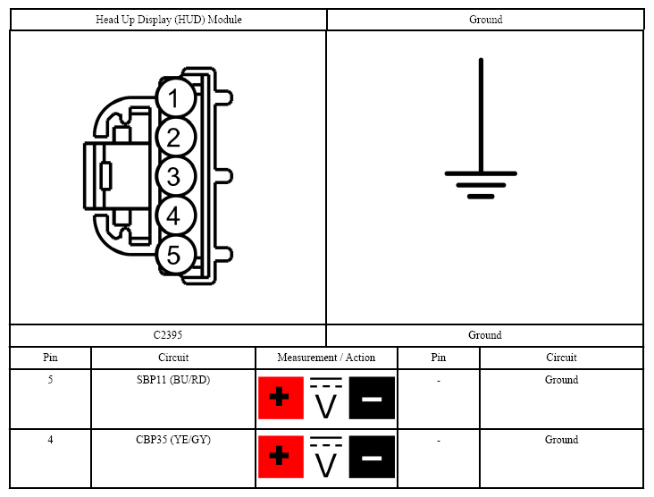
- CHECK THE Head Up Display (HUD) MODULE VOLTAGE SUPPLY
- Ignition OFF.
- Disconnect: Head Up Display (HUD) Module.
- Ignition ON.
- Measure:
 Courtesy of FORD MOTOR CO.
- Are the voltages greater than 11 volts?
- Yes:
GO to step 5
.
- No:
VERIFY the Body Control Module (BCM) fuse 11 (10A) or 35 (5A) is OK. If OK, REPAIR the circuit in question for an open. If not OK, REFER to the SYSTEM WIRING DIAGRAMS
to identify the possible causes of the circuit short.
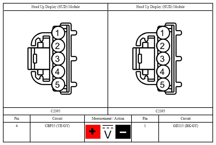
- CHECK THE Head Up Display (HUD) MODULE GROUND CIRCUIT
- Measure:
 Courtesy of FORD MOTOR CO.
- Is the voltage greater than 11 volts?
- Yes:
GO to step 6
.
- No:
REPAIR the circuit
- CHECK FOR CORRECT Head Up Display (HUD) MODULE OPERATION
- Disconnect and inspect the Head Up Display (HUD) module connector.
- Repair:
- corrosion (install new connector or terminals - clean module pins)
- damaged pins - install new terminals/pins
- pushed-out pins - install new pins as necessary
- Reconnect the Head Up Display (HUD) module connector. Make sure it seats and latches correctly.
- Operate the system and determine if the concern is still present.
- Is the concern still present?
- Yes:
CHECK On-Line Automotive Service Information System (OASIS) for any applicable Technical Service Bulletins (TSBs). If a Technical Service Bulletin (TSB) exists for this concern, DISCONTINUE this test and FOLLOW Technical Service Bulletin (TSB) instructions. If no Technical Service Bulletins (TSBs) address this concern, INSTALL a new Head Up Display (HUD) module. REFER to HEAD UP DISPLAY (HUD) MODULE .
- No:
The system is operating correctly at this time. The concern may have been caused by module connections. ADDRESS the root cause of any connector or pin issues.