- Remove the battery tray. For additional information, refer to BATTERY MOUNTING AND CABLES
.
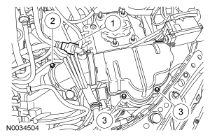
- Remove the air cleaner resonator.
- Disconnect the crankcase ventilation hose.
- Disconnect the air cleaner outlet hose.
- Remove the bolts and pull out the air cleaner resonator.
 Courtesy of FORD MOTOR CO.
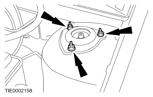
- Loosen the LH strut and spring assembly top mount nuts by 5 turns.
 Courtesy of FORD MOTOR CO.
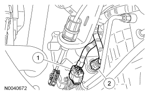
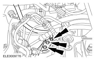
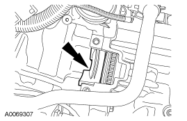
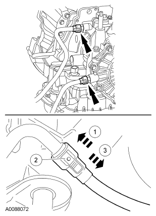
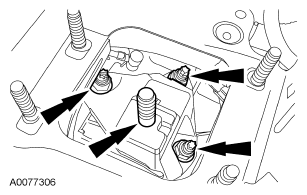
- Disconnect the electrical connectors.
- Transmission range (TR) sensor electrical connector.
- Transaxle solenoid electrical connector.
 Courtesy of FORD MOTOR CO.
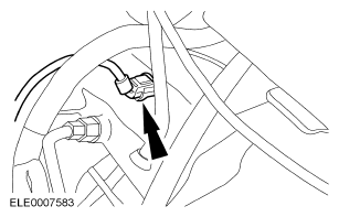
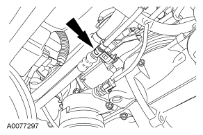
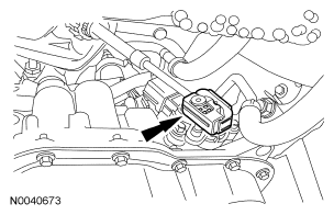
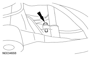
- Disconnect the turbine shaft speed (TSS) sensor electrical connector.
 Courtesy of FORD MOTOR CO.
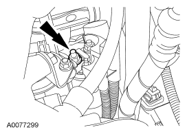
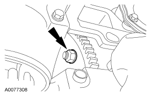
- Remove the nut from the electrical connector bracket.
 Courtesy of FORD MOTOR CO.
- Remove the nut and position the electrical connector bracket aside.
 Courtesy of FORD MOTOR CO.
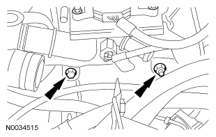
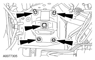
- Remove the upper center converter housing bolts.
 Courtesy of FORD MOTOR CO.
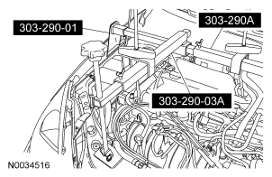
- Using the special tool, secure the engine.
 Courtesy of FORD MOTOR CO.
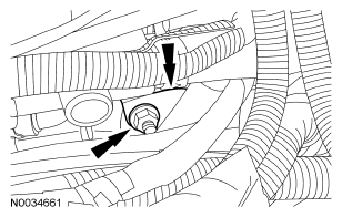
- Remove the fluid filler tube and shift cable bracket bolts.
 Courtesy of FORD MOTOR CO.
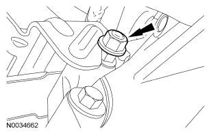
- Remove the nut and bracket from the starter stud.
 Courtesy of FORD MOTOR CO.
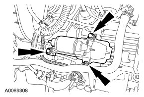
- Remove the starter nuts, then disconnect the wiring from the starter.
 Courtesy of FORD MOTOR CO.
NOTE:
Unplug the oil sending unit to remove the starter from its location.
- Remove the 3 starter bolts and starter.
 Courtesy of FORD MOTOR CO.
- Remove the starter isolator.
 Courtesy of FORD MOTOR CO.
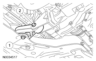
- Remove the engine RH support insulator.
- Remove the insulator bolt and nut.
- Remove the insulator bolt.
 Courtesy of FORD MOTOR CO.
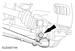
- Disconnect the LH stabilizer bar at the strut.
 Courtesy of FORD MOTOR CO.
- Remove the LH tie-rod end nut.
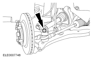 Courtesy of FORD MOTOR CO.
- Remove the RH tie-rod end nut.
 Courtesy of FORD MOTOR CO.
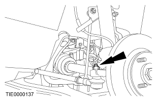
- Using the special tool, disconnect both of the tie-rods from the knuckles.
 Courtesy of FORD MOTOR CO.
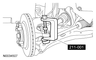
- Disconnect both of the lower control arms from the knuckles.
 Courtesy of FORD MOTOR CO.
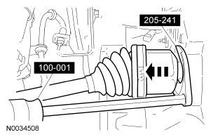
- Remove the mounting bracket nuts, then remove the bracket from the RH halfshaft intermediate bearing.
 Courtesy of FORD MOTOR CO.
- Remove the RH halfshaft. Position it aside and support the halfshaft with mechanic's wire.
 Courtesy of FORD MOTOR CO.
CAUTION:
Support the halfshaft. The inner joint must not be bent more than 18 degrees. The outer joint must not be bent more than 45 degrees.
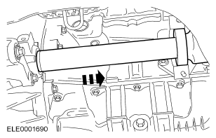
- Using the special tools, remove the LH halfshaft from the transaxle.
- Allow the oil to drain into a suitable container.
 Courtesy of FORD MOTOR CO.
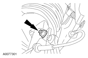
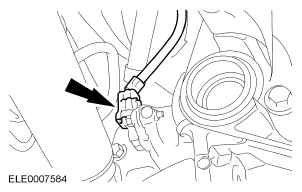
- Disconnect the output shaft speed (OSS) sensor electrical connector.
 Courtesy of FORD MOTOR CO.
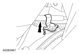
- Unbolt the shift cable clip.
 Courtesy of FORD MOTOR CO.
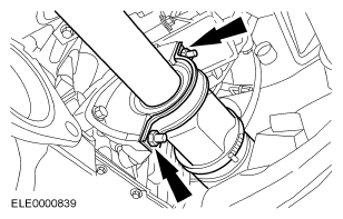
- Disconnect the transmission fluid cooler lines from the transaxle.
- Slide the connector fitting into the cooler line.
- Press the yellow release button.
- Pull the connector fitting from the cooler line.
 Courtesy of FORD MOTOR CO.
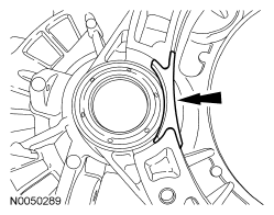
- Disconnect the shift cable from the manual control lever.
 Courtesy of FORD MOTOR CO.
CAUTION:
Only rotate the engine in a clockwise direction or engine damage will occur.
NOTE:
Mark one stud and the flexplate for assembly reference.
- Rotate the crankshaft to gain access to the converter nuts, then remove the 4 nuts.
 Courtesy of FORD MOTOR CO.
- Remove the engine rear mount nuts and remove the rear mount.
 Courtesy of FORD MOTOR CO.
- Using the engine support bar, lower the engine and transaxle assembly slightly.
- Remove the engine rear mount bracket nuts and remove the bracket.
 Courtesy of FORD MOTOR CO.
- Remove the fluid filler tube.
- Remove the bolt at the base and pull out the tube and position it aside.
 Courtesy of FORD MOTOR CO.
- Secure the transaxle with a high-lift jack using a safety strap.
NOTE:
Note the location of the different length bolts for installation.
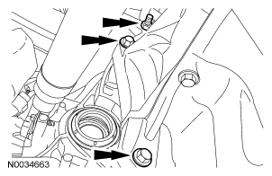
- Remove the 3 converter housing bolts.
 Courtesy of FORD MOTOR CO.
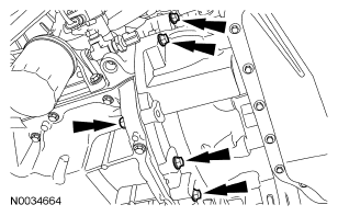
- Remove the 5 converter housing bolts.
 Courtesy of FORD MOTOR CO.
- Separate the transaxle from the engine and lower the transaxle.
- If replacement of the transaxle is required, remove the differential opening cover.
 Courtesy of FORD MOTOR CO.
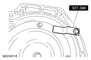
- Install the special tool, to prevent damage to the torque converter.
 Courtesy of FORD MOTOR CO.