Test A: Starter Does Not Crank
- If vehicle is equipped with Passive Anti-Theft System (PATS), check system for Diagnostic Trouble Codes (DTCs). See PASSIVE ANTI-THEFT SYSTEMS - SABLE & TAURUS article in ACCESSORIES & EQUIPMENT. Repair as necessary.
- Verify battery condition. Battery voltage should be 12 volts or more. Load test battery at approximately one-half cold cranking amperage rating. See load tester manufacturer's instructions. If battery voltage is less than 12 volts or loaded battery voltage is less than 9.6 volts, service battery or charging system as necessary.
- Measure the resistance between the negative battery post and the battery ground cable connection on the engine. If resistance is less than 5 ohms, go to next step. If resistance is 5 ohms or more, replace battery ground cable and check system operation.
- Measure resistance between ground and starter motor case. If resistance is less than 5 ohms, go to next step. If resistance is greater than 5 ohms, verify starter is mounted correctly. Repair as necessary. If starter is mounted properly, remove starter and clean mounting surfaces. See STARTER MOTOR under REMOVAL & INSTALLATION.
- Turn ignition off and place transaxle in Park or Neutral. Remove starter solenoid plastic safety cap (install when testing is complete). Measure voltage between starter motor terminal "B" and ground. See Figure. If battery voltage is present, go to next step. If battery voltage is not present, replace battery positive cable and check system operation.
- Connect one end of a jumper wire to starter "B" terminal. Momentarily touch other end of jumper wire to starter "S" terminal. If starter motor operates, go to next step. If starter motor does not operate, replace starter motor and check system operation. See STARTER MOTOR under REMOVAL & INSTALLATION.
- Disconnect starter motor "S" connector. Turn ignition switch to START position and measure voltage between starter motor electrical connector terminal "S" (White/Pink wire) and ground. If battery voltage is present with ignition switch in START position, clean starter motor terminal "S". Check wires and connections for looseness or corrosion. Repair as necessary. Check system operation. If battery voltage is not present, go to next step.
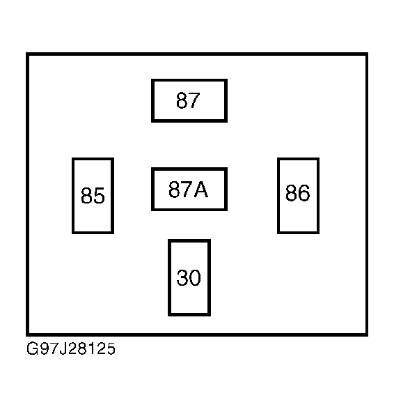
- Remove starter relay from battery junction box. With transaxle in Park or Neutral and ignition switch in START position, measure voltage between starter relay electrical connector terminal No. 85 (Tan/Red wire) and ground. See Fig 1. If battery voltage is present, go to next step. If battery voltage is not present, go to step 13.
 Courtesy of FORD MOTOR CO.
- Measure voltage between starter relay connector terminal No. 87 and ground. See Fig 1. If battery voltage is present, go to next step. If battery voltage is not present, check fuse No. 7 (40-amp) in battery junction box. If fuse is okay, repair open in Light Green/Violet wire. See WIRING DIAGRAMS .
- Measure resistance of starter relay ground circuit, between starter relay electrical connector terminal No. 86 (Pink wire) and ground with ignition switch in START position. If resistance is less than 5 ohms, go to step 12. If resistance is more than 5 ohms, go to next step.
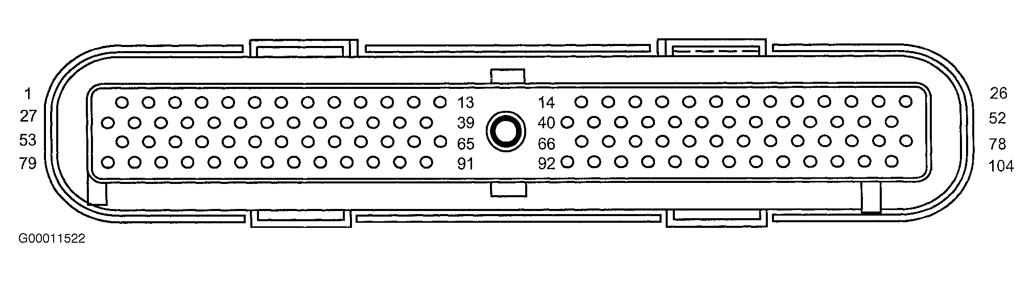
- Disconnect PCM connector. Measure resistance of Pink wire between starter relay connector terminal No. 86 and PCM connector terminal No. 44. See Fig 2. If resistance is less than 5 ohms, replace PCM and check system operation. If resistance is more than 5 ohms, repair Pink wire and check system operation.
 Courtesy of FORD MOTOR CO.
- Measure resistance between starter relay connector terminal No. 30 (White/Pink wire) and starter motor connector terminal "S". If resistance is less than 5 ohms, install new starter relay and check system operation. If resistance is more than 5 ohms, repair White/Pink wire and check system operation.
- Remove fuse No. 21 (15-amp) from smart junction box. Hold ignition switch in START position and measure voltage between fuse No. 37 input cavity and ground. If battery voltage is present, go to next step. If battery voltage is not present, go to step 18.
- Check fuse No. 21 (15-amp). If fuse is okay, go to next step. If fuse is faulty, go to step 17.
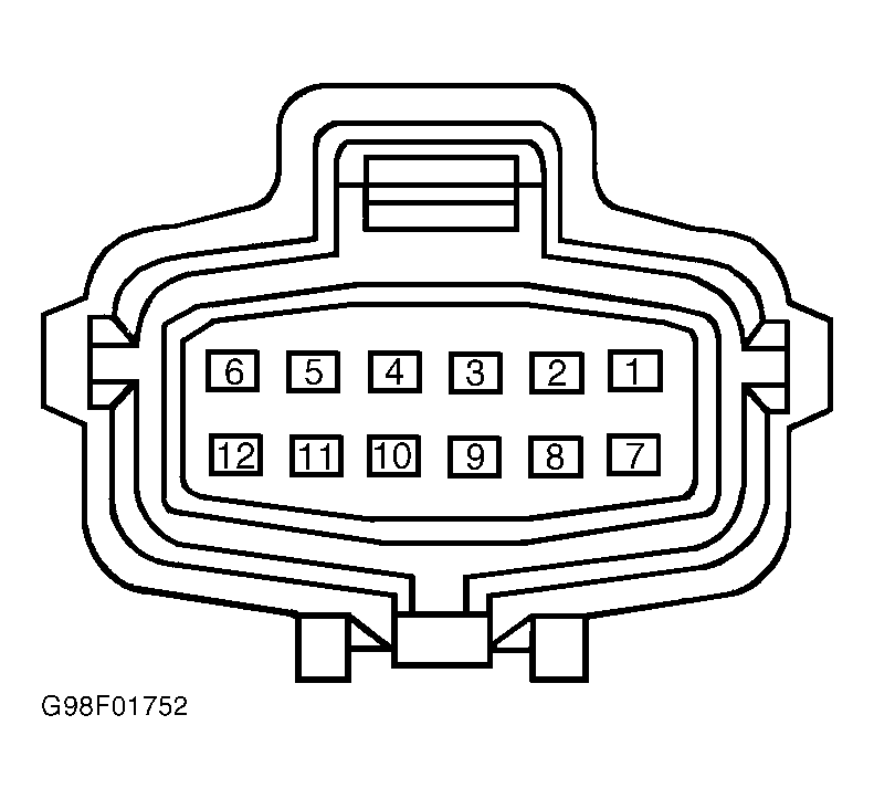
- Install fuse No. 21. Disconnect Digital Transmission Range (DTR) sensor. Measure voltage between DTR sensor electrical connector terminal No. 10 (Brown/Pink wire) and ground with ignition switch in START position. See Fig 3. If battery voltage is present, go to next step. If battery voltage is not present, repair Brown/Pink wire and check system operation.
 Courtesy of FORD MOTOR CO.
- Measure resistance of Tan/Red wire between starter relay connector terminal No. 85 and DTR sensor connector terminal No. 12. If resistance more than 5 ohms, repair Tan/Red wire and check system operation. If resistance is 5 ohms or less, check DTR sensor adjustment. Adjust as necessary, using DTR Sensor Alignment Tool (T97L-70010-A). If adjustment is okay, replace DTR sensor and check system operation.
- Ensure starter relay is removed. Measure resistance between DTR sensor terminal No. 10 (Brown/Pink wire) and ground. Measure resistance between DTR sensor terminal No. 12 (Tan/Red wire) and ground. If resistance is 10,000 ohms or more, check DTR sensor adjustment. Adjust as necessary, using DTR Sensor Alignment Tool (T97L-70010-A). If adjustment is okay, replace DTR sensor and check system operation. If resistance is less than 10 k/ohms, repair short to ground on affected circuit.
- Disconnect ignition switch connector. Measure voltage between ignition switch connector terminal B4 (Light Green/Purple wire) and ground. If battery voltage is present, go to next step. If battery voltage is not present, inspect fuse No. 7 (40-amp) in battery junction box. If fuse is okay, repair Light Green/Purple wire.
- Test ignition switch. See STEERING COLUMN SWITCHES - SABLE & TAURUS article in ACCESSORIES & EQUIPMENT. Replace as necessary. If ignition switch is okay, repair open or short in Red/Light Blue wire between ignition switch connector and fuse No.7.