Test A: Top Does Not Operate
- Ensure parking brake is applied. Turn ignition switch to RUN position. Press convertible top switch to RAISE and LOWER positions while listening for convertible top motor operation. If convertible top motor does not operate in both directions, go to next step. If convertible top motor operates in both directions, go to TEST C: TOP DOES NOT RAISE COMPLETELY
.
- Turn ignition switch to LOCK position. Remove convertible top switch. Convertible top switch is located in center console, next to parking brake lever. Disconnect convertible top switch 5-pin harness connector. Turn ignition switch to RUN position. Measure voltage between ground and convertible top switch harness connector terminal No. 4 (White/Pink wire). See Fig 1
. If more than 10 volts exist, go to next step. If 10 volts or less exist, repair open in White/Pink wire between convertible top switch and fuse No. 20 (15-amp) in Central Junction Box (CJB). CJB is located behind left side of instrument panel, left of steering column. See WIRING DIAGRAMS
.
- Turn ignition switch to LOCK position. Reconnect convertible top switch harness connector. Remove convertible top raise relay. Convertible top raise relay is located behind top center of rear seat, left of convertible top motor. Turn ignition switch to RUN position. Press and hold convertible top switch to RAISE position. Measure voltage between ground and convertible top raise relay connector terminal No. 85 (Violet wire). See Fig 2
. If more than 10 volts exist, go to next step. If 10 volts or less exist, go to step 5
.
- Turn ignition switch to LOCK position. Remove convertible top lower relay. Convertible top lower relay is located behind rear seat, left of convertible top motor. Turn ignition switch to RUN position. Press and hold convertible top switch to LOWER position. Measure voltage between ground and convertible top lower relay connector terminal No. 85 (Gray/Light Blue wire). See Fig 2
. If more than 10 volts exist, go to step 7
. If 10 volts or less exist, go to step 6
.
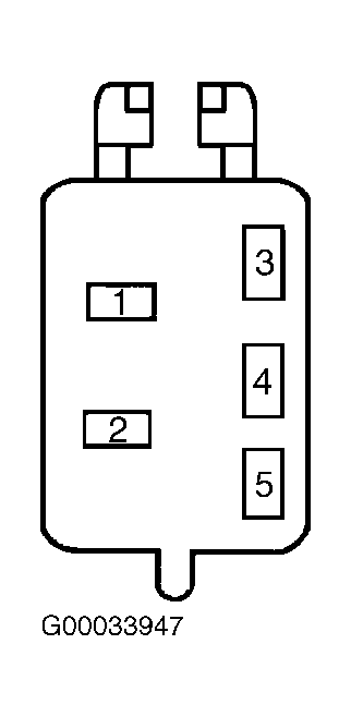 Courtesy of FORD MOTOR CO.
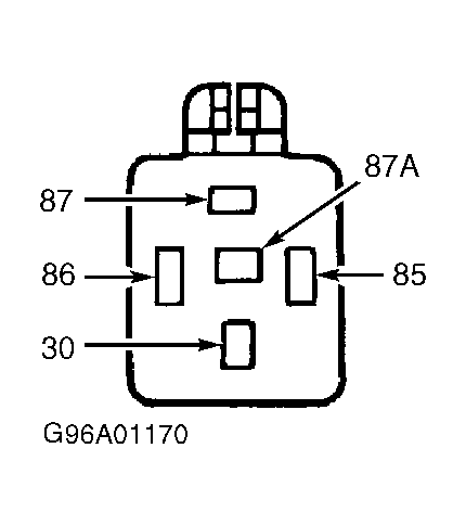 Courtesy of FORD MOTOR CO.
- Turn ignition switch to LOCK position. Disconnect convertible top switch harness connector. Measure resistance of Violet wire between convertible top switch harness connector terminal No. 3 and convertible top raise relay connector terminal No. 85. If resistance is less than 5 ohms, replace convertible top switch. See REMOVAL & INSTALLATION
. If resistance is 5 ohms or more, repair open in Violet wire between convertible top switch and convertible top raise relay. See WIRING DIAGRAMS
.
- Turn ignition switch to LOCK position. Disconnect convertible top switch harness connector. Measure resistance of Gray/Light Blue wire between convertible top switch harness connector terminal No. 5 and convertible top lower relay connector terminal No. 85. If resistance is less than 5 ohms, replace convertible top switch. See REMOVAL & INSTALLATION
. If resistance is 5 ohms or more, repair open in Gray/Light Blue wire between convertible top switch and convertible top lower relay. See WIRING DIAGRAMS
.
- Measure voltage between ground and convertible top raise and lower relays connector terminals No. 87 (Red/Light Blue wires). If more than 10 volts exist, go to next step. If 10 volts or less exist, repair open in appropriate Red/Light Blue wire between convertible top raise and/or lower relay and CONV TOP circuit breaker (25-amp) in Battery Junction Box (BJB). BJB is located in left side of engine compartment, forward of strut tower. See WIRING DIAGRAMS
.
- Turn ignition switch to LOCK position. Measure resistance between ground and convertible top raise and lower relays connector terminals No. 87A (Black wires). If resistance is less than 10 k/ohms at both terminals, go to next step. If resistance is 10 k/ohms or more at either terminal, repair open in appropriate Black wire between convertible top raise and/or lower relay and ground. Ground point is located in left rear of vehicle. See WIRING DIAGRAMS
.
- Measure resistance between ground and convertible top raise and lower relays connector terminals No. 86 (Violet/White wires). If resistance is 5 ohms or more, go to next step. If resistance is less than 5 ohms, go to step 11
.
- Disconnect parking brake switch harness connector. Measure resistance between parking brake switch harness connector Light Blue/Black wire terminal and raise and lower relays connector terminals No. 86 (Violet/White wires). If resistance is less than 5 ohms, replace parking brake switch. If resistance is 5 ohms or more, repair open in Violet/White or Light Blue/Black wire(s) between appropriate relay and parking brake switch. See WIRING DIAGRAMS
.
- Reinstall raise and lower relays. Disconnect convertible top motor harness connector. Convertible top motor harness connector is located in front center of luggage compartment. Measure resistance between ground and convertible top motor harness connector Yellow wire terminal. If resistance is 5 ohms or more, go to next step. If resistance is less than 5 ohms, go to step 13
.
- Remove convertible top lower relay. Measure resistance of Yellow wire between lower relay connector terminal No. 30 and convertible top motor harness connector. If resistance is less than 5 ohms, replace convertible top lower relay. If resistance is 5 ohms or more, repair open in Yellow wire between convertible top lower relay and convertible top motor. See WIRING DIAGRAMS
.
- Turn ignition switch to RUN position. Measure voltage between ground and convertible top motor harness connector Yellow wire terminal. Press and hold convertible top switch to LOWER position. If more than 10 volts exist, go to next step. If 10 volts or less exist, replace lower relay.
- Turn ignition switch to LOCK position. Measure resistance between ground and convertible top motor harness connector Red wire terminal. If resistance is 5 ohms or more, go to next step. If resistance is less than 5 ohms, go to step 16
.
- Remove convertible top raise relay. Measure resistance of Red wire between convertible top raise relay connector terminal No. 30 and convertible top motor harness connector. If resistance is less than 5 ohms, replace raise relay. If resistance is 5 ohms or more, repair open in Red wire between convertible top raise relay and convertible top motor. See WIRING DIAGRAMS
.
- Turn ignition switch to RUN position. Press and hold convertible top switch in RAISE position. Measure voltage between ground and convertible top motor harness connector Red wire terminal. If more than 10 volts exist, replace convertible top motor. See REMOVAL & INSTALLATION
. If 10 volts or less exist, replace raise relay.