Rear Window Does Not Defog
- Perform CENTRAL TIMER MODULE SELF-TEST
under COMPONENT TESTS. If self-test is okay, go to next step. If self-test is not okay, see appropriate MODULE COMMUNICATIONS NETWORK article.
- Turn ignition on. Locate defogger relay. See COMPONENT LOCATIONS
. Press rear defogger switch. If defogger relay clicks, go to next step. If defogger relay does not click, go to step 12
.
- Turn ignition off. Using an ohmmeter, check fuse F7 (40-amp). See COMPONENT LOCATIONS
. If fuse is okay, go to next step. If fuse is not okay, replace fuse. If fuse fails again, repair short to ground in Red wire and retest system operation.
- Turn ignition off. Disconnect defogger relay. Using voltmeter, measure voltage between Central Junction Box (CJB) defogger relay connector terminal No. 3 (Red wire) and ground. See Fig 1
. If voltage is greater than 10 volts, go to next step. If voltage is less than 10 volts, repair open in Red wire and retest system operation.
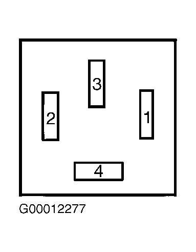 Courtesy of FORD MOTOR CO.
- Using ohmmeter, check fuse F49 (25-amp). See COMPONENT LOCATIONS
. If fuse is okay, go to step 7
. If fuse is not okay, replace fuse. If fuse fails again, repair short to ground in Green/Blue wire and retest system operation.
- Using ohmmeter, check fuse F51 (7.5-amp). See COMPONENT LOCATIONS
. If fuse is okay, go to step 9
. If fuse is not okay, replace fuse. If fuse fails again, repair short to ground in Green/Blue wire and retest system operation.
- Reconnect defogger relay. Disconnect rear window defogger grid wire connector on left side of rear window. Turn ignition on. Activate rear window defogger. Using a voltmeter, measure voltage between Green/Blue wire at rear window defogger wire connector and ground. If voltage is greater than 10 volts, go to next step. If voltage is less than 10 volts, repair open or short in Green/Blue wire and retest system operation.
- Turn ignition off. Reconnect rear window defogger grid wire connector. Disconnect rear window defogger grid wire connector on right side of rear window. Using an ohmmeter, measure resistance between Black wire at rear window defogger grid wire connector and ground. If resistance is less than 5 ohms, replace rear window. If resistance is greater than 5 ohms, repair open in Black wire and retest system operation.
- Perform DEFOGGER RELAY TEST
under COMPONENT TESTS. If defogger relay tests okay, go to next step. If defogger relay does not test okay, replace defogger relay and retest system operation.
- Turn ignition on. Using a voltmeter, measure voltage between CJB defogger relay connector terminal No. 1 (Green/Yellow wire) and ground. See Fig 1
. If voltage is greater than 10 volts, go to next step. If voltage is less than 10 volts, repair open in Green/Red wire and retest system operation.
- Turn ignition off. Reconnect defogger relay. Disconnect Central Timer Module (CTM) from CJB. Disconnect rear defogger switch harness connector C380. Using an ohmmeter, measure resistance between Black/Blue wire at rear defogger switch harness connector C380 terminal No. 3 and CJB CTM connector terminal No. 19. See Fig 2
and Fig 3
. If resistance is less than 5 ohms, go to next step. If resistance is greater than 5 ohms, repair open in Black/Blue wire and retest system operation.
- Reconnect CTM to CJB. Disconnect rear defogger switch harness C380. Perform REAR DEFOGGER SWITCH TEST
. If rear defogger switch tests okay, go to next step. If rear defogger switch does not test okay, replace rear defogger switch and retest system operation.
- Using an ohmmeter, measure resistance between Black/Orange wire at defogger switch harness connector C380 terminal No. 12 and ground. See Fig 2
. If resistance is less than 5 ohms, verify customer concern. If resistance is greater than 5 ohms, repair open in Black/Orange wire and retest system operation.
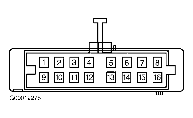 Courtesy of FORD MOTOR CO.
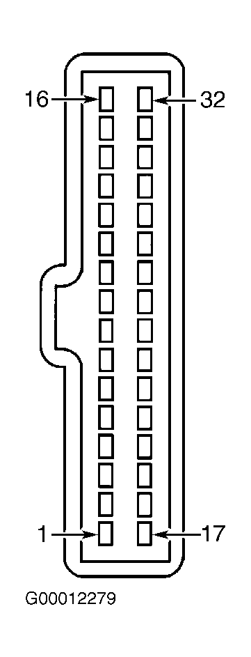 Courtesy of FORD MOTOR CO.