Test A: Both Side Mirrors Inoperative
- Turn ignition switch to LOCK position. Remove and check fuse No. 1 (7.5-amp) from Central Junction Box (CJB), located below left side of instrument panel. If fuse is okay, go to next step. If fuse is open, install NEW fuse and recheck system operation. If fuse opens again, repair short to ground in Orange/Light Green wire or power distribution circuit. See
POWER DISTRIBUTION article in WIRING DIAGRAMS.
- Remove driver's door trim panel. Disconnect mirror control switch 8-pin harness connector C507. Measure voltage between ground and mirror control switch harness connector C507 terminal No. 1 (Orange/Light Green wire). See Fig 1
. If more than 10 volts exists, go to next step. If 10 volts or less exists, repair open in Orange/Light Green wire. See WIRING DIAGRAMS
.
- Measure resistance between ground and mirror control switch harness connector C507 terminal No. 5 (Black wire). If resistance is less than 5 ohms, replace mirror control switch. If resistance is 5 ohms or greater, repair open or high resistance in Black wire. See WIRING DIAGRAMS
.
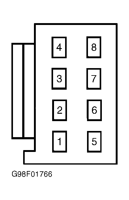 Courtesy of FORD MOTOR CO.