Test B: Charge Warning Indicator On With Engine Running
- Perform GENERATOR NO-LOAD TEST
under ON-VEHICLE TESTING. If voltage is less than specified, go to next step. If voltage is as specified, repair short to ground in White/Blue wire, battery junction box or instrument cluster. See WIRING DIAGRAMS
. Check system operation.
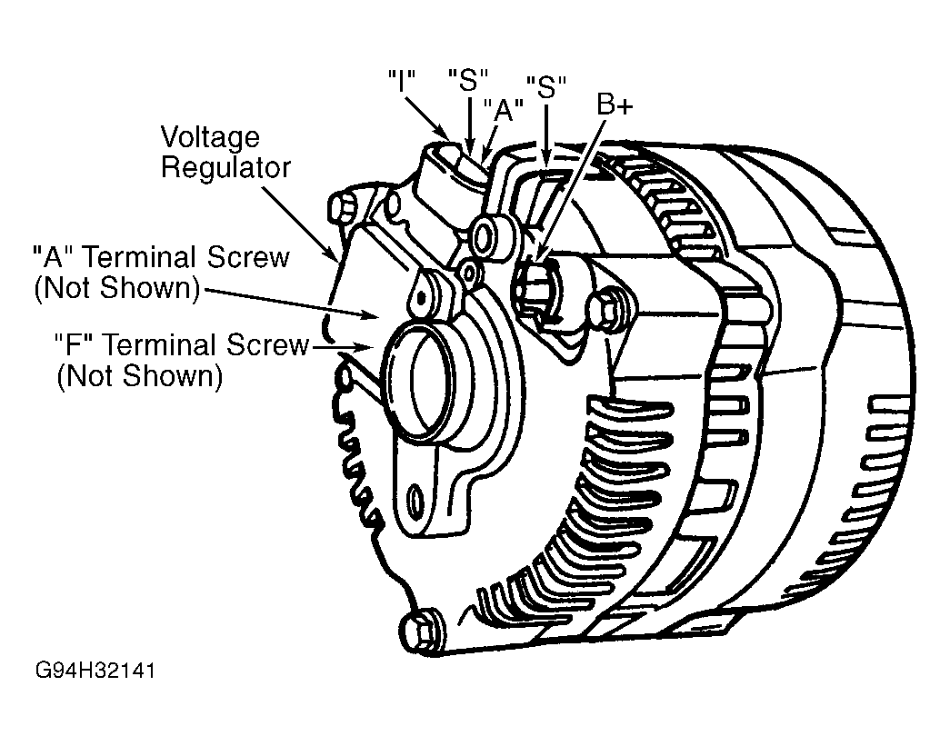
- Turn ignition off. Measure voltage between generator terminal "A" and ground. See Figure
. If battery voltage is present, go to next step. If battery voltage is not present, repair White/Green wire or battery junction box. See WIRING DIAGRAMS
. Check system operation.
- Turn ignition off. Disconnect generator 3-pin connector. Turn ignition on, engine off and observe charge warning indicator. If indicator does not illuminate, go to next step. If indicator illuminates, repair short to ground in White/Blue wire, battery junction box or instrument cluster. See WIRING DIAGRAMS
. Check system operation.
- Turn ignition off. Reconnect generator 3-pin connector. Disconnect generator 1-pin connector (Orange wire). Install a jumper wire between 1-pin connector terminal and positive battery terminal. Observe charge warning indicator with ignition on, engine off. If indicator illuminates, go to next step. If indicator does not illuminate, go to step 6
.
- Turn ignition off. Disconnect generator 3-pin connector. Measure resistance of Orange wire between generator 3-pin connector terminal and generator 1-pin connector terminal. If resistance is less than 5 ohms, replace voltage regulator and check system operation. See VOLTAGE REGULATOR
under REMOVAL & INSTALLATION. If resistance is 5 ohms or greater, repair high resistance or open in Orange wire. See WIRING DIAGRAMS
. Check system operation.
- Start engine and measure voltage between generator "S" terminal and ground. See Fig 1
. If voltage is one-half battery voltage or greater, go to next step. If voltage is less than one-half battery voltage, system is okay at this time. Restore connections and check system operation.
- Run engine at 1500 RPM with all accessories off. Measure voltage between generator terminal B+ and ground. See Fig 1
. If voltage is 14.1 volts or greater, go to TEST A: SYSTEM OVERCHARGES
. If voltage is less than 14.1 volts, replace voltage regulator. See VOLTAGE REGULATOR
under REMOVAL & INSTALLATION.
 Courtesy of FORD MOTOR CO.