Test D: Transmission Range Sensor
- Check Digital TR Sensor Adjustment
Check digital TR sensor adjustment. See FORD F4E-III (MAZDA FA4A-EL) OVERHAUL article. If digital TR sensor does not require adjustment, go to next step. If digital TR sensor requires adjustment, adjust to specification and repeat QUICK TEST
under DIAGNOSIS & TESTING. Ensure no DTCs exist.
- Check For Intermittent Circuit Concerns
With ignition switch in OFF position, install NGS tester to DLC. Turn ignition switch to ON position. Using scan tool manufacturers instructions, monitor TR PID gear position and voltage. While monitoring scan tool, tap on digital TR sensor and wiggle digital TR sensor connector and wiring harness. If PID values do not change, go to next step. If PID values change, poor connection, open or short exists. Repair as necessary. Recheck operation.
- Check Digital TR Sensor Input To PCM
With NGS tester connected, monitor TR PID V (voltage) on scan tool and move gearshift lever through all gears. Voltage should be less than .5 volt in "P" or "N" position and more than 4.5 volts in all other positions. If voltage is as specified, replace PCM. If voltage is not as specified, go to next step.
- Check Digital TR Sensor Circuits To PCM For Opens Or Shorts
Turn ignition switch to OFF position. Disconnect transaxle harness connector and PCM harness connector. Install breakout box to PCM harness connector and leave PCM disconnected. Using DVOM, measure resistance between specified digital TR sensor harness connector terminals and breakout box terminals. See Fig 1
. Use DIGITAL TR SENSOR CIRCUIT RESISTANCE
table for proper digital TR sensor circuit resistances. If resistances are as specified, replace PCM. Repeat QUICK TEST
under DIAGNOSIS & TESTING. If resistances are not as specified, repair affected circuit. Repeat QUICK TEST
.
DIGITAL TR SENSOR CIRCUIT RESISTANCE
| Measure Between TR Sensor
& Breakout Box Terminals No. (Wire Color) |
Ohms |
| 2 & 32 (Red/Green) |
Less Than 5 |
| 3 & 7 (Brown/Green) |
Less Than 5 |
| 4 & 6 (Brown/Blue) |
Less Than 5 |
| 8 & 9 (Brown/Yellow) |
Less Than 5 |
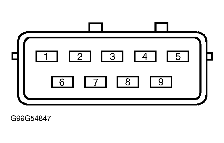 Courtesy of FORD MOTOR CO.