Starter Does Not Crank
- Check Start Signal At Solenoid
Disconnect Red/Light Blue wire from starter solenoid "S" terminal. While holding ignition switch in Start position, measure voltage between ground and Red/Light Blue wire to starter solenoid. If battery voltage does not exist, go to next step. If battery voltage exists, ensure battery cable and ground connections are okay, repair if necessary. If connections are okay, replace starter and solenoid.
- Check Maxi-fuse
Check Maxi-fuse "C" (60-amp) in underhood fuse/relay box. If fuse is blown, go to next step. If fuse is okay, go to step 4).
- Check Black/Orange Wire For Short To Ground
Measure resistance between output side of Maxi-fuse "C" cavity to ground. If resistance is less than 10 k/ohms, repair Black/Orange wire for short to ground. If resistance is greater than 10 k/ohms, replace fuse and check system operation.
- Check Ignition Switch Feed
Measure voltage between Black/Orange wire at ignition switch harness connector and ground. If battery voltage exists, go to next step. If battery voltage does not exist, repair open Black/Orange wire between Maxi-fuse "C" and ignition switch harness connector. Restore electrical connections and check system operation.
- Check Ignition Switch Operation
Restore all electrical connections. While holding ignition switch in Start position, measure voltage between White/Pink wire at ignition switch harness connector and ground. If battery voltage does not exist, replace ignition switch. If battery voltage exists and vehicle is equipped with anti-theft system, go to next step. If battery voltage exists and vehicle is not equipped with anti-theft system, go to step 11).
- Check White/Pink Wire
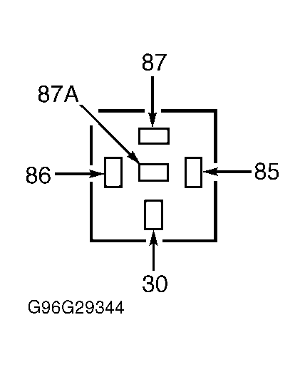
While holding ignition switch in START position, measure voltage between starter relay harness connector terminal No. 30 (White/Pink wire) and ground. See Fig 1
. If battery voltage does not exist, replace ignition switch. If battery voltage exists, go to next step. If battery voltage does exist, repair open White/Pink wire.
 Courtesy of FORD MOTOR CO.
- Check Fuse No. 2
Check fuse No. 2 in instrument panel fuse panel. If fuse is okay, go to next step. If fuse is blown, replace fuse. If fuse fails again, check Black/Light Blue wire for short to ground. Restore electrical connections and check system operation.
- Check Start Signal To Relay
While holding ignition switch in START position, measure voltage between starter relay harness connector terminal No. 85 (Black/Light Blue wire) and ground. See Fig 1
. If battery voltage exists, go to next step. If battery voltage does not exist, repair open White/Pink or Black/Light Blue wire. See WIRING DIAGRAMS
. Restore electrical connections and check system operation.
- Check Starter Relay
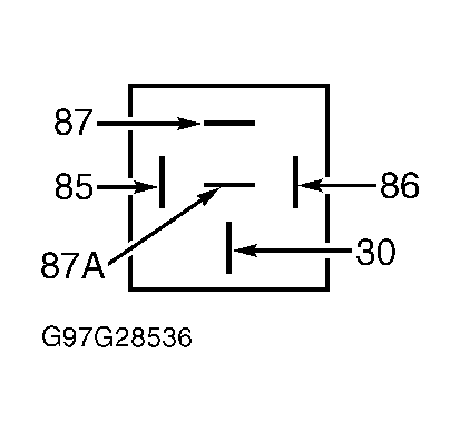
Remove starter relay. Measure resistance between relay terminals No. 30 and 87. See Fig 2
. Resistance should be greater than 10 k/ohms. Connect battery voltage and ground to relay terminals No. 85 and 86. Measure resistance between relay terminals No. 30 and 87. Resistance should be less than 5 ohms. Replace relay if necessary. If relay is okay, go to next step.
 Courtesy of FORD MOTOR CO.
- Check Light Green/Purple Wire
Hold ignition switch in Start position. Measure resistance between Light Green/Purple wire at starter relay harness connector terminal and ground. If resistance is less than 5 ohms, go to next step. If resistance is greater than 5 ohms, check for open Light Green/Purple wire. If light Green/Purple wire is okay, fault is related to anti-theft system. See ANTI-THEFT SYSTEM - ACTIVE
article.
- Check Start Signal To TR Sensor
Restore all electrical connections. Disconnect Transmission Range (TR) sensor harness connector. While holding ignition switch in START position, measure voltage between White/Pink wire at TR sensor harness connector and ground. If battery voltage exists, go to next step. If battery voltage does not exist, repair open White Pink/Wire. Restore electrical connections and check system operation.
- Check Red/Light Blue Wire
Measure resistance of Red/Light Blue wire between TR sensor harness connector and starter solenoid. If resistance is greater than 5 ohms, repair open Red/Light Blue wire. If resistance is less than 5 ohms, ensure TR sensor is properly adjusted. If adjustment is okay, replace TR sensor. Restore electrical connections and check system operation.