No Communication With Pats Module
- Check Power Window Operation
- Turn ignition on. Operate power window one touch down feature. If power window one touch down feature operates properly, go to next step. If power window one touch down feature does not operate properly, replace instrument panel fuse block fuse No. 15 (5-amp). Retest system operation. If fuse fails again, go to step 6).
- Check White/Yellow Wire For Voltage
- Turn ignition off. Disconnect PATS module connector C268. PATS module is located behind center of instrument panel. Measure voltage between ground and terminal No. 15 (White/Yellow wire) at PATS module connector C268. See Figure
. If voltage is 10 volts or less, go to next step. If voltage is more than 10 volts, go to step 5).
- Check White/Yellow Wire For Open
- Ensure ignition is off. Disconnect instrument panel fuse block connector C243. Measure resistance in White/Yellow wire between PATS module connector C268 terminal No. 15 and instrument panel fuse block connector C243 terminal No. 25. If resistance is less than 5 ohms, go to next step. If resistance is more than 5 ohms, repair open in White/Yellow wire between PATS module and instrument panel fuse block. Clear DTCs and retest system operation.
- Check Instrument Panel Fuse Block For Open
- Measure resistance between instrument panel fuse block fuse No. 15 terminal No. 1 and instrument panel fuse block terminal No. 25. See Fig 1
. If resistance is less than 5 ohms, go to step 7). If resistance is 5 ohms or more, replace instrument panel fuse block. Clear DTCs and retest system operation.
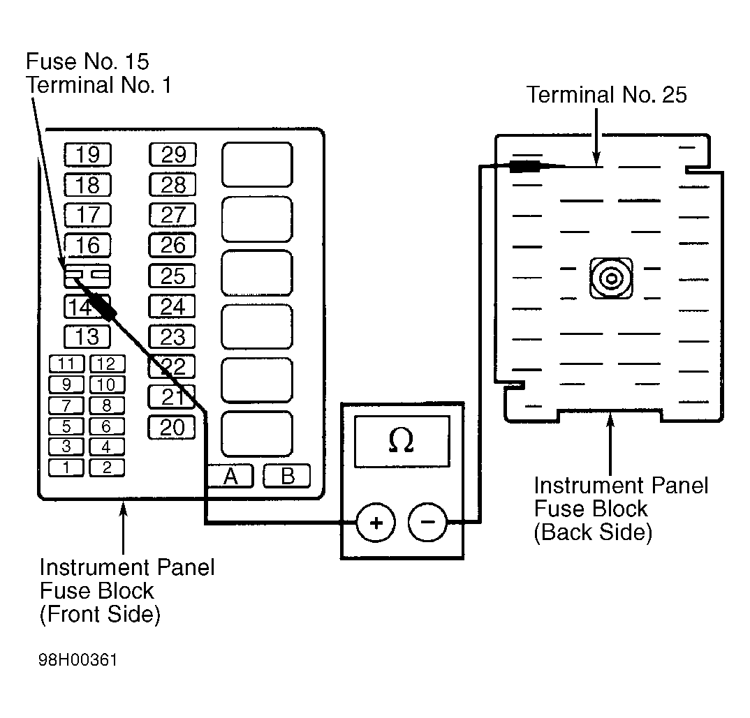 Courtesy of FORD MOTOR CO.
- Check Black/White Wire For Open
- Ensure ignition is off. Measure resistance between ground and PATS module connector C268 terminal No. 7 (Black/White wire). See Figure
. If resistance is less than 5 ohms, go to step 9). If resistance is 5 ohms or more, repair open in Black/White wire. Clear DTCs and retest system operation.
- Check White/Yellow Wire For Short To Ground
- Disconnect PATS module connector C268. PATS module is located behind center of instrument panel. Disconnect Generic Electronic Module (GEM) 18-pin connector C267 (located in instrument panel fuse block). Replace instrument panel fuse block fuse No. 15 (5-amp). Using ohmmeter, check condition of fuse No. 15 (5-amp). If fuse is okay, reconnect PATS module connector C268 and go to next step. If fuse is not okay, go to step 8).
- Check PATS Module For Short To Ground
- Replace instrument panel fuse block fuse No. 15 (5-amp). Using ohmmeter, check condition of fuse No. 15 (5-amp). If fuse is okay, replace GEM. Clear DTCs and retest system operation. If fuse is not okay, replace PATS module. Reprogram a NEW and spare ignition key. See KEY INITIALIZATION and SPARE KEY PROGRAMMING under SERVICE PROCEDURES
. Clear DTCs and retest system operation.
- Check Instrument Panel Fuse Block For Short To Ground
- Disconnect instrument panel fuse block connector C243. Replace instrument panel fuse block fuse No. 15 (5-amp). Using ohmmeter, check condition of fuse No. 15 (5-amp). If fuse is not okay, repair short to ground in White/Yellow wire between PATS module and instrument panel fuse block. If fuse is okay, replace instrument panel fuse block. Clear DTCs and retest system operation.
- Check Red/Light Green Wire For Voltage
- Turn ignition on. Measure voltage between ground and PATS module connector C268 terminal No. 16 (Red/Light Green wire). See Figure
. If voltage is more than 10 volts, replace PATS module. Reprogram a NEW and spare ignition key. See KEY INITIALIZATION and SPARE KEY PROGRAMMING under SERVICE PROCEDURES. Clear DTCs and retest system operation. If voltage is 10 volts or less, replace fuse No. 30 (30-amp) in instrument panel fuse block, or repair Red/Light Green wire between instrument panel fuse block and PATS module. Retest system operation.