Pinpoint Test "B" - System Does Not Activate Properly
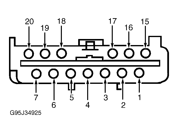
- Turn ignition off. Disconnect Anti-Theft Control Module (ATCM) and Electronic Door Lock Control Processor (EDLCP) connectors. See Figure
and Figure
. Connect jumper between EDLCP connector terminals No. 3 (Red/Orange wire) and No. 6 (Pink/Orange wire) and ground. Measure resistance between ground terminal No. 26 (Black/White wire) and ATCM connector terminal No. 8 (Red/Orange wire). Repeat procedure between ground and ATCM terminal No. 7 (Pink/Orange wire) . Remove jumpers. If resistance is 10 k/ohms or less on both circuits, go to next step. If any resistance is more than 10 k/ohms, repair open on circuits No. 118 (Pink/Orange wire) and/or No. 163 (Red/Orange wire) and retest system.
- Disconnect ATCM and EDLCP connectors. Turn ignition to run. Measure voltage between ATCM connector terminals No. 4 (Yellow/Black wire) and No. 26 (Black/White wire). If voltage is 9 volts or more, go to step 4). If voltage is less than 9 volts, go to next step.
- Check 10-amp fuse No. 12 in fuse junction panel. If fuse is blown, replace fuse and retest system. If fuse is good, repair open in circuit No. 137 (Yellow/Black wire) and retest system.
- Connect EDLCP connector. Unlock driver door lock with key. With door lock cylinder rotated to unlock, measure resistance between ATCM connector terminals No. 6 and No. 26 (Black/White wire). Repeat procedure for passenger door. If resistance is 10 k/ohms or less at both doors, go to step 6). If resistance is more than 10 k/ohms for both doors, go to next step.
- Disconnect driver door lock cylinder switch. Check for continuity across door lock cylinder switch terminals while turning lock cylinder with key. Repeat procedure for passenger door lock cylinder switch. If there is continuity with key in unlock position and no continuity with key in lock position, repair open in circuit No. 25 (Dark Green/Purple wire) and retest system. If continuity is not as stated above, replace damaged door lock cylinder switch(es) and retest system.
- Connect Anti-Theft Control Module connectors. Ensure voltage at Anti-Theft Control Module connector C2, terminal No. 9 (Pink/Black wire) is less than 2 volts and that a momentary battery voltage signal is present at connector C2, terminal No. 8 (Red/Orange wire) when doors are unlocked via keyless entry unlock code or remote transmitter UNLOCK button. If voltage reading is correct, replace ATCM and retest system. If voltage reading is incorrect, go to next step.
- Disconnect ATCM connectors. Ensure voltage at ATCM connector C2, terminal No. 9 (Pink/Black wire) is less than 2 volts and that a momentary battery voltage signal is present at connector C2, terminal No. 8 (Red/Orange wire) when doors are unlocked via keyless entry unlock code or remote transmitter UNLOCK button. If voltage reading is correct, replace ATCM and retest system. If voltage reading is incorrect, problem is in RKE system. See appropriate KEYLESS ENTRY SYSTEM - REMOTE article.
 Courtesy of FORD MOTOR CO.