Bore & Face RUNOUT
- Lift clutch pedal to its uppermost position to disengage clutch pedal quadrant adjuster pawl from clutch pedal adjuster quadrant assembly. Hold and secure in this position with a rubber band or tape. Disengage clutch release lever cable from clutch release lever.
- Remove transmission and flywheel housing. See CLUTCH ASSEMBLY
under REMOVAL & INSTALLATION. Remove clutch release hub, bearing, clutch pressure plate and clutch disc. Inspect and clean front and rear face of flywheel housing, flywheel housing bore surface and rear face of engine cylinder block. Also inspect and clean engine rear plate, flywheel and engine flywheel housing-to-block dowels. Install engine rear plate and flywheel housing to engine.
- Position Magnetic Base/Flex Arm (D78P-4201-C). Position dial indicator so indicator button contacts circumference just outside transmission pilot hole. Tighten flex arm. Push crankshaft rearward to remove any end play. Zero dial indicator.
- Holding crankshaft in rearward position, rotate crankshaft through one complete revolution. Dial indicator should return to zero after one revolution unless end play or loose universal clamp has affected reading.
- Record greatest variation between indicator readings for one revolution. Repeat procedure to verify reading. After completion of flywheel housing face runout check, install Clutch Housing Alignment Adapter (T75l-4201-A) to dial indicator and position assembly to check bore runout. Install rubber band to lever as shown, prior to installation of lever, to preload dial indicator for bore readings. See Fig 1
.
- Zero dial indicator. Rotate crankshaft through one revolution. Record greatest variation between indicator readings for complete crankshaft revolution. Repeat procedure to verify readings. If maximum variation in face runout exceeds .010" (.25 mm) or bore runout exceeds .015" (.38 mm), replace flywheel housing.
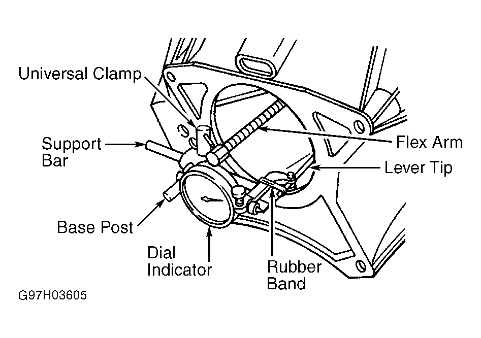 Courtesy of FORD MOTOR CO.