Pinpoint Test "A" No Module Communication
- Turn ignition off. Check 5-amp fuse No. 15 and 20-amp fuse No. 18. If fuses are good, go to step 3). If fuses are bad, go to next step.
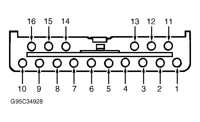
- Disconnect PATS module connector. See Fig 1
. Measure resistance between ground and PATS module connector terminals No. 15 (Dark Blue/Orange wire) and No. 16 (Red/Light Green wire). If resistance is 10 k/ohms or more, replace PATS module, fuses and retest system. If resistance is less than 10 k/ohms, repair short to ground in circuits No. 196 (Red/Light Green wire) and/or No 16 (Red/Light Green wire) and retest system.
- Turn ignition off. Disconnect PATS module connector. Turn ignition on. Measure voltage between ground and PATS module connector terminals No. 15 (Dark Blue/Orange wire) and No. 16 (Red/Light Green wire). If battery voltage is not present at both terminals, go to next step. If battery voltage is present at both terminals, go to step 5).
- Turn ignition off. Remove 5-amp fuse No. 15 from fuse junction panel. Disconnect PATS module connector. Measure resistance between output side of fuse No. 15 and PATS module connector terminal No. 15 (Dark Blue/Orange wire). Measure resistance between output side of fuse No. 18 and PATS module connector terminal No. 16 (Red/Light Green wire). If resistance of both circuits is 5 ohms or less, go to next step. If resistance of both circuit is more than 5 ohms, repair open in affected circuit(s) and retest system.
- Turn ignition off. Disconnect PATS module connector. Measure resistance between PATS connector terminal No. 3 (Black/White wire) and ground. If resistance is 5 ohms or less, problem is in data communication link. See MODULE COMMUNICATIONS NETWORK article. If resistance is more than 5 ohms, repair open in circuit No. 397 (Black/White wire).
 Courtesy of FORD MOTOR CO.